


1/5 scale K2 black panther tank

 03-13-2023, 12:35 AM
#27

Thread Starter

The tank manufacturer decided to manufacture and install the caterpillar of the 2023 1/5 scale Black Panther tank (project name: ic2504) by casting method. The optimal method is to increase production efficiency and reduce the number of iterations.
The shape of the track is somewhat different from the actual one, but it is strong and has increased assembly efficiency.
The production is outsourced processing, and the outsourced production has been requested today.
Regards,
Young
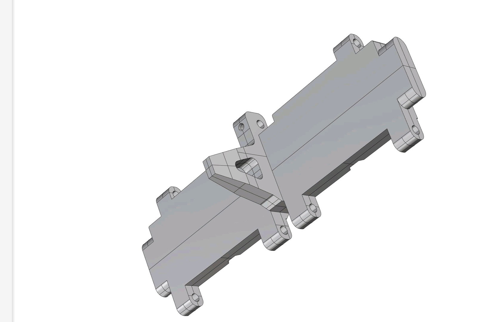
Upper shape of caterpillar
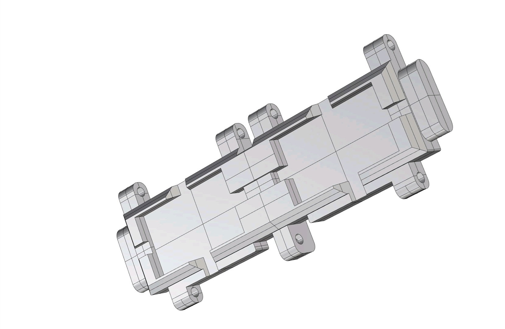
the lower appearance of the caterpillar
The shape of the track is somewhat different from the actual one, but it is strong and has increased assembly efficiency.
The production is outsourced processing, and the outsourced production has been requested today.
Regards,
Young
Upper shape of caterpillar
the lower appearance of the caterpillar
Last edited by PE YOUNG; 03-13-2023 at 12:53 AM.
03-13-2023, 02:46 AM
#28
Some pretty awesome work there. Very motivating for me!
03-19-2023, 02:45 PM
#29
Thread Starter
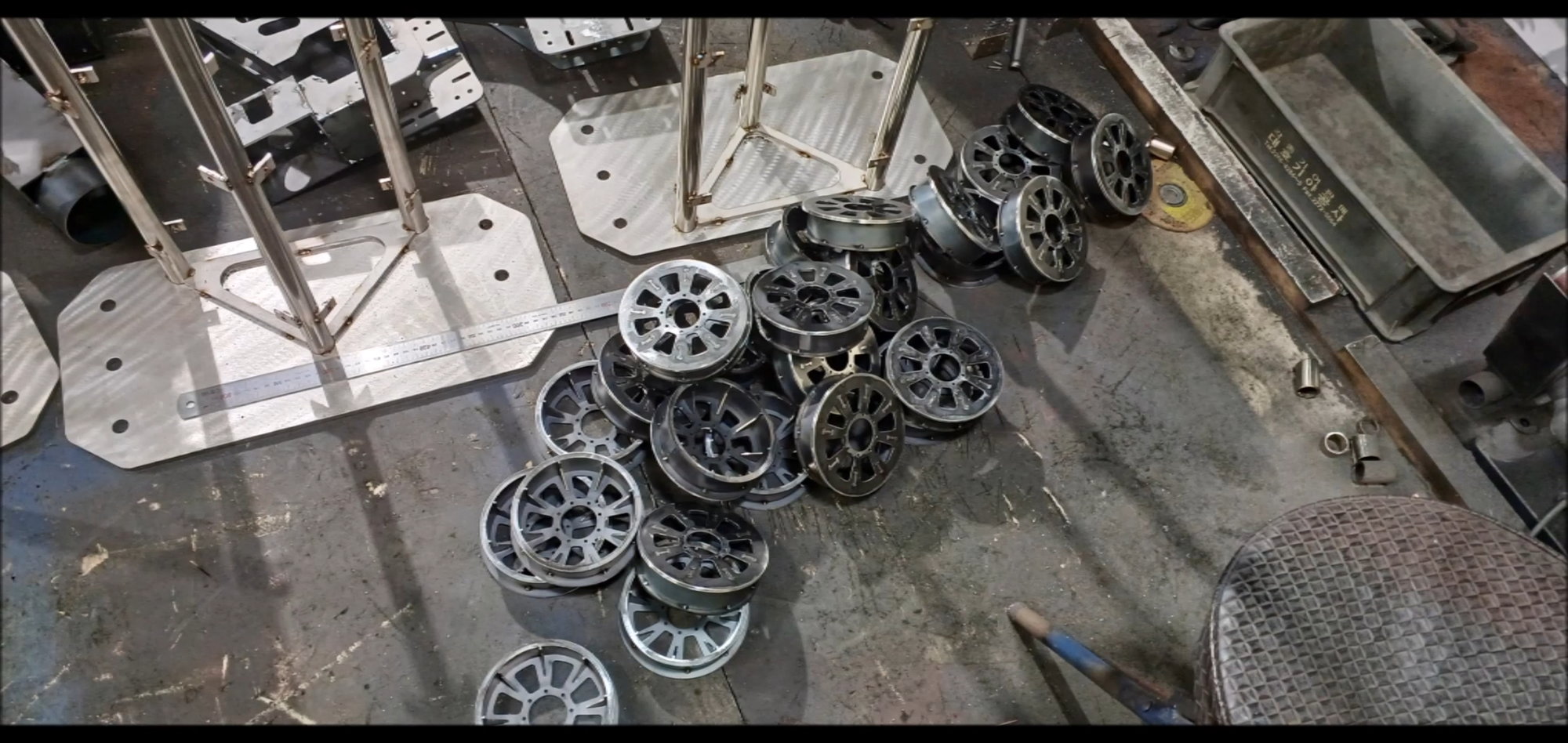
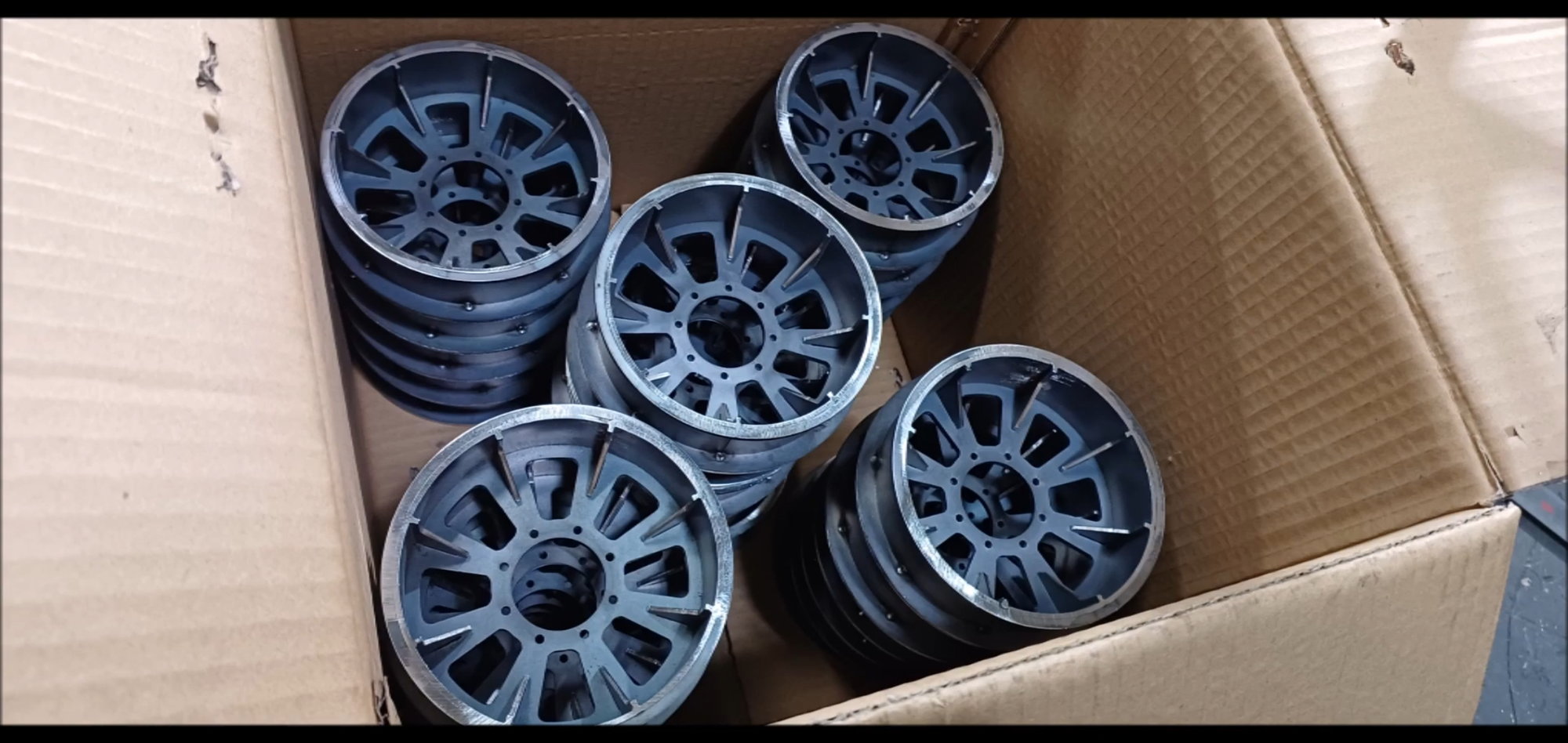
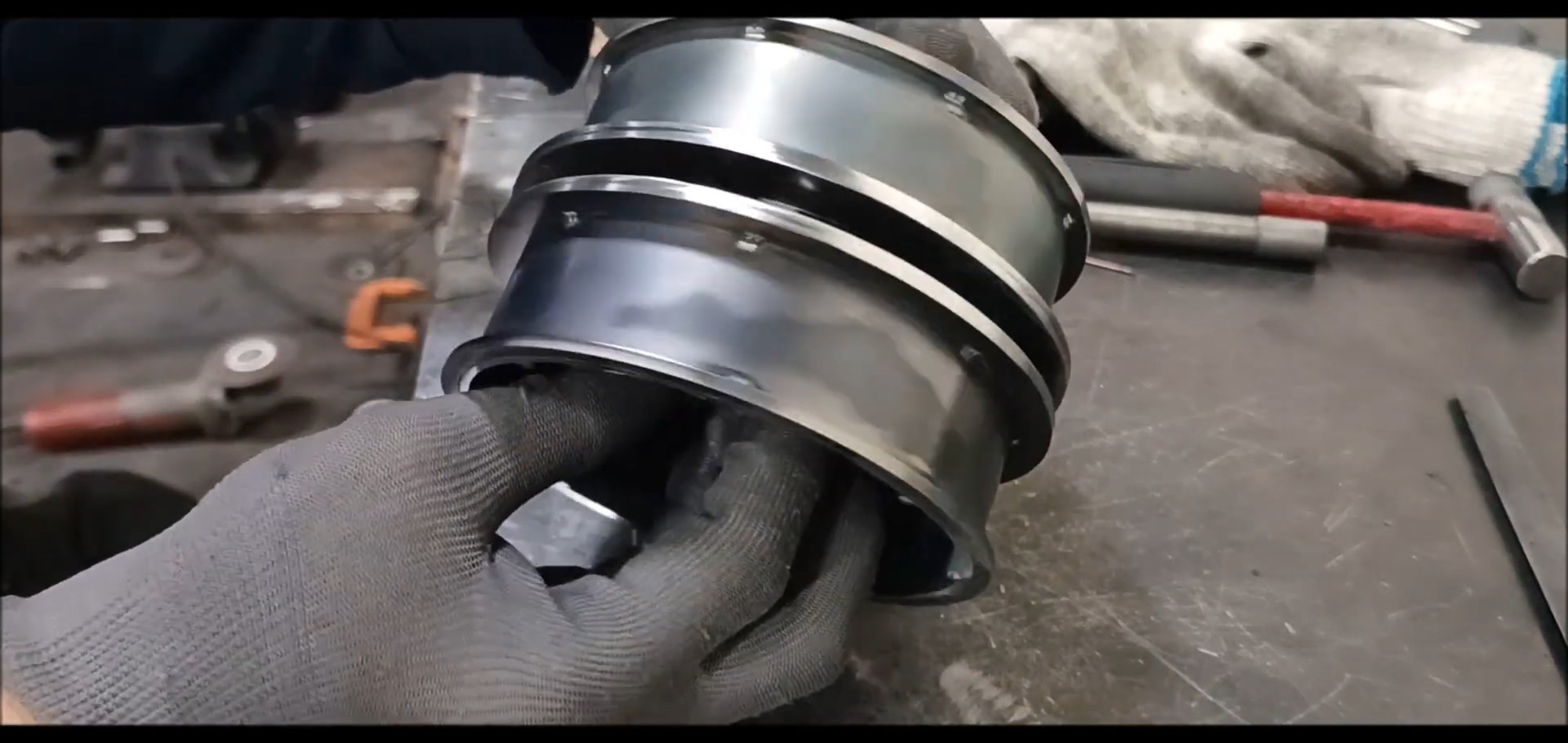
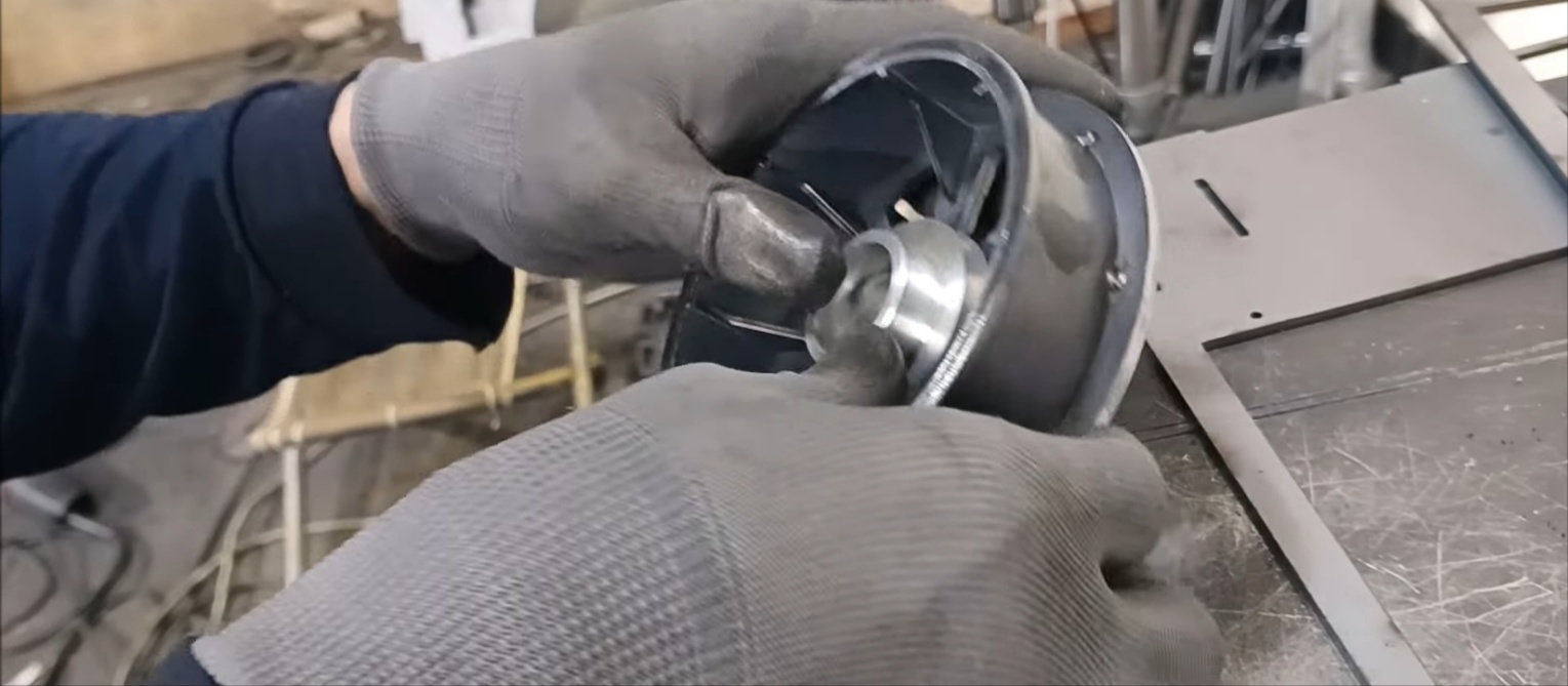
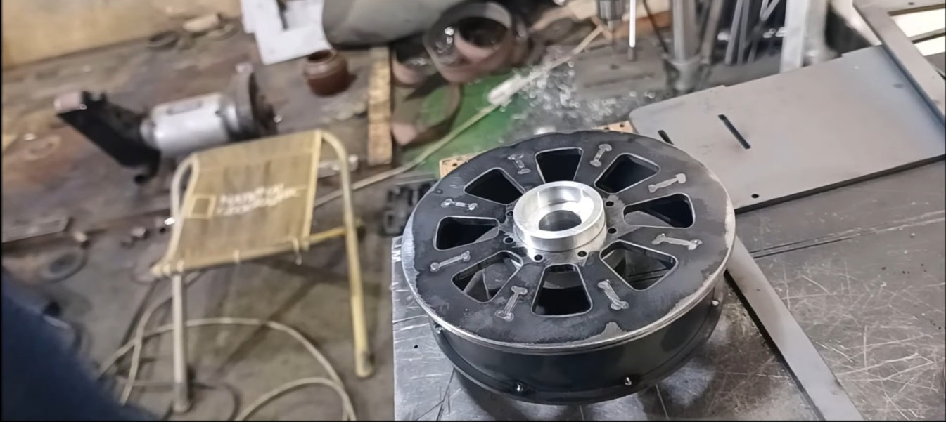
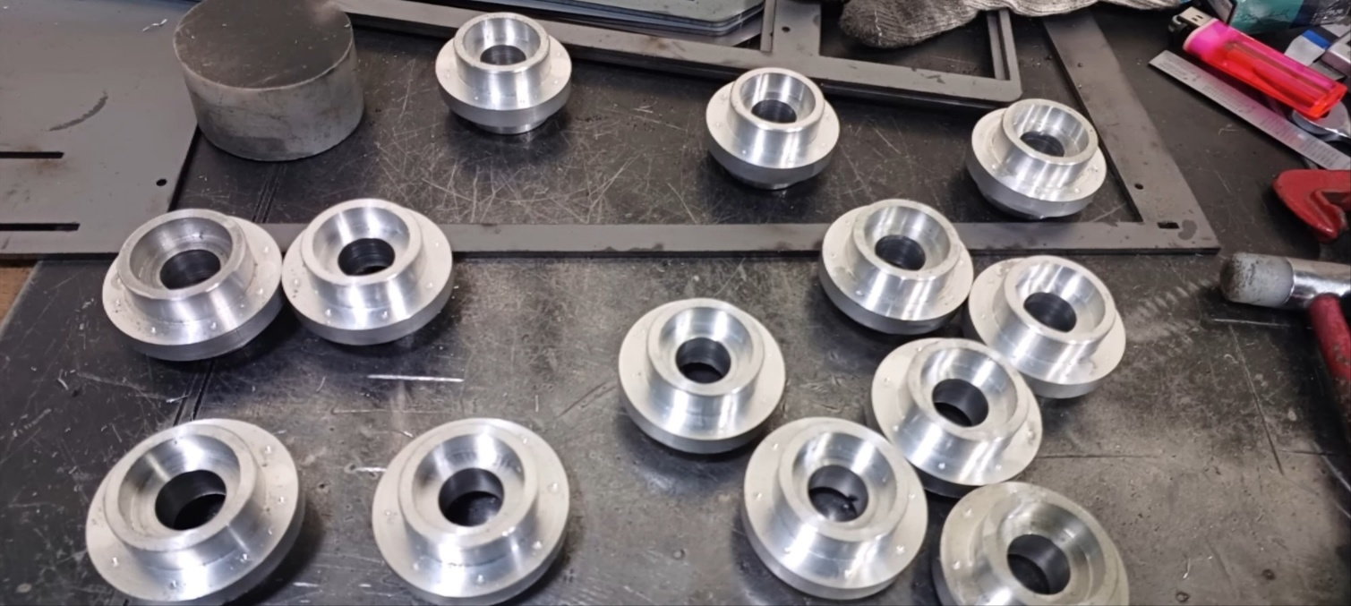
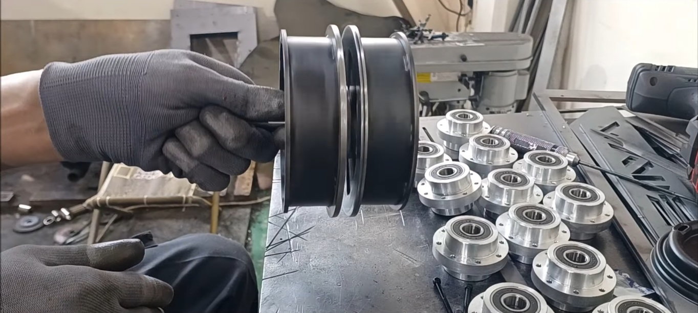
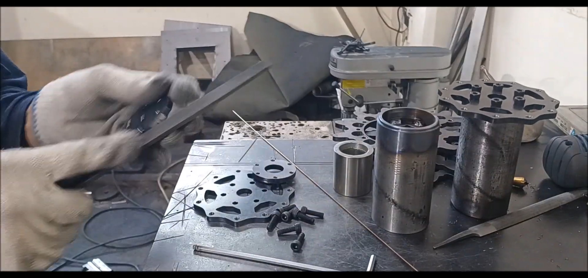
This week, the shape of the bogie wheel has been completed, it has been trimmed, and the production of the bearing insertion type connection joint has been completed.
Regards,
Young
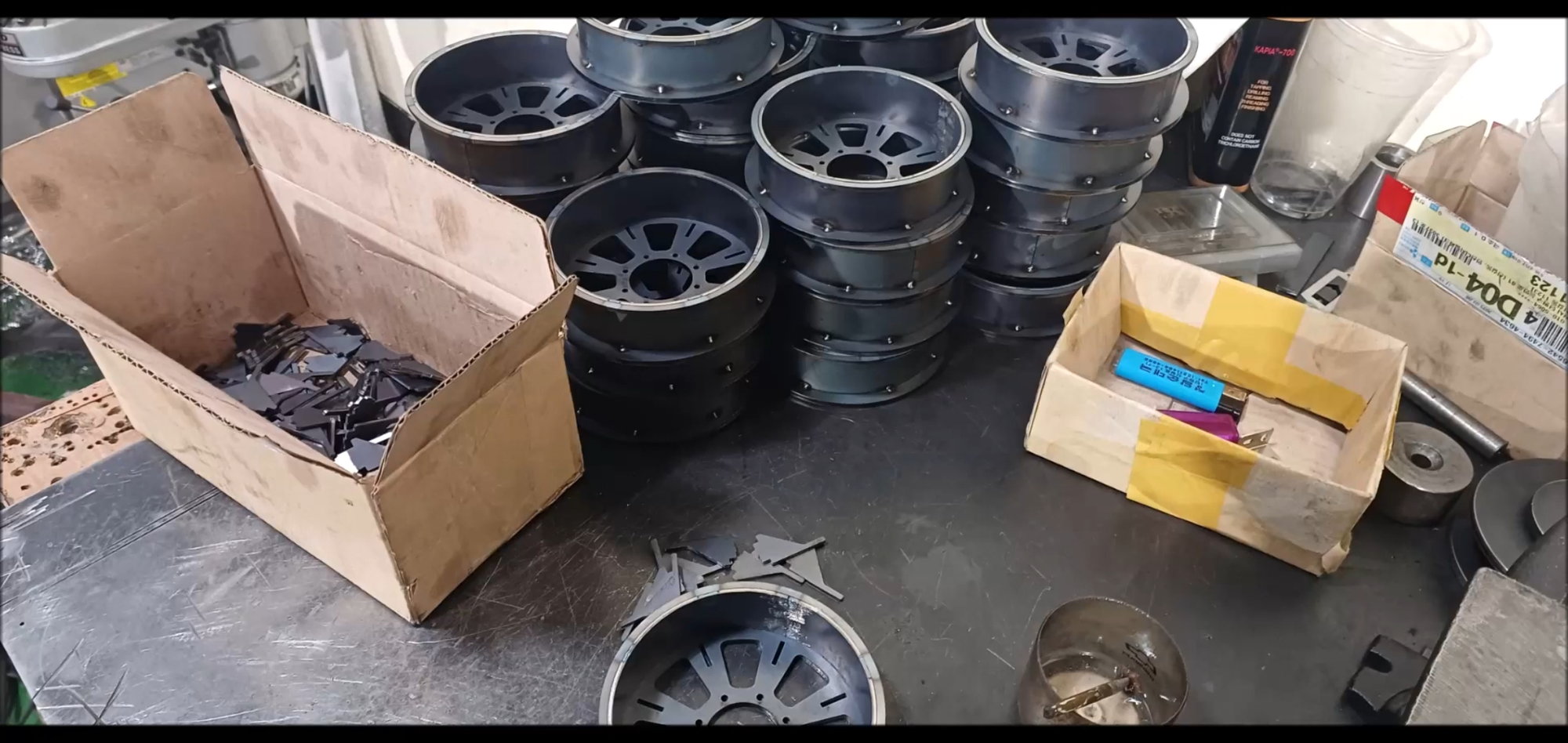
Bogie Wheel Work Continues Last Week
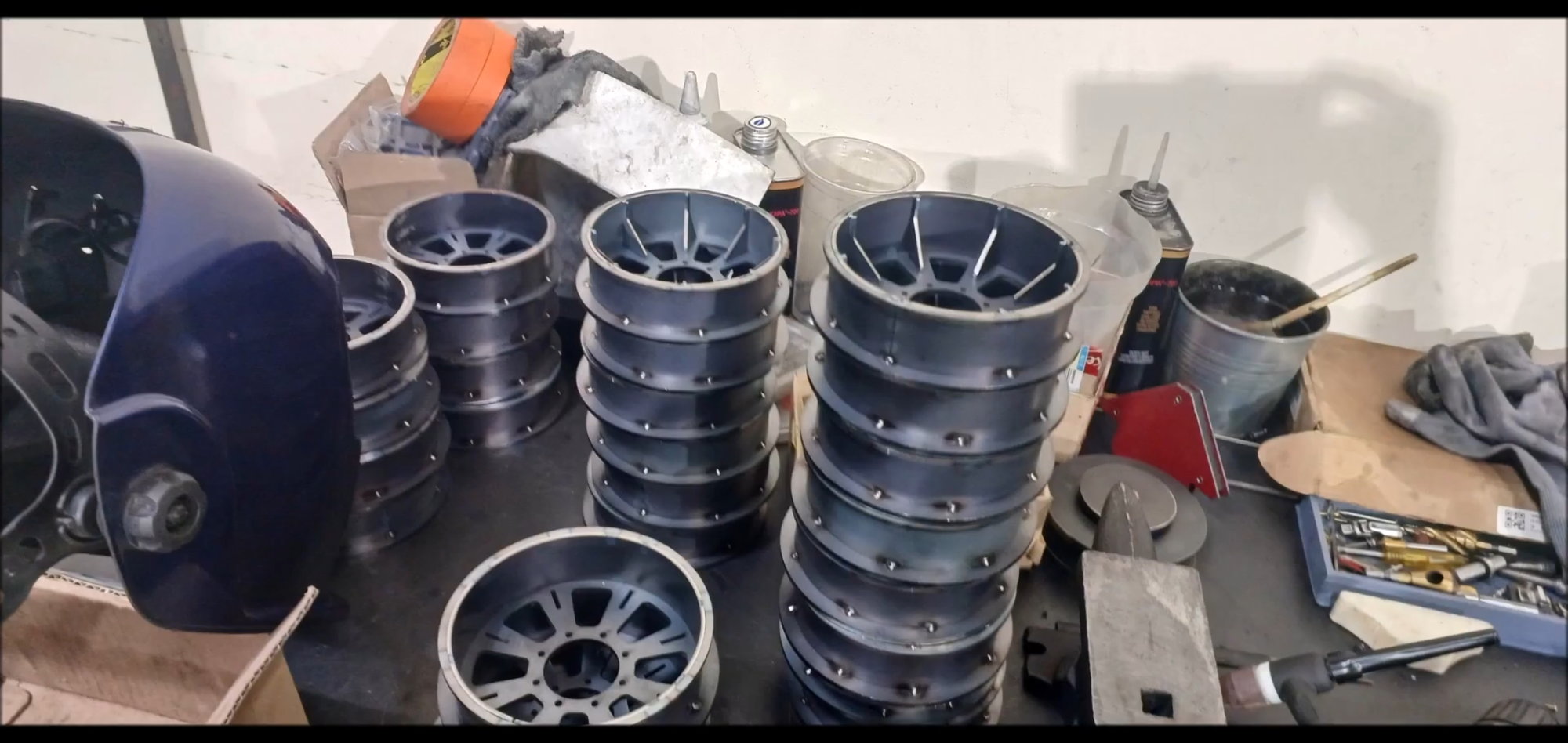
Install spokes on the viewing wheel
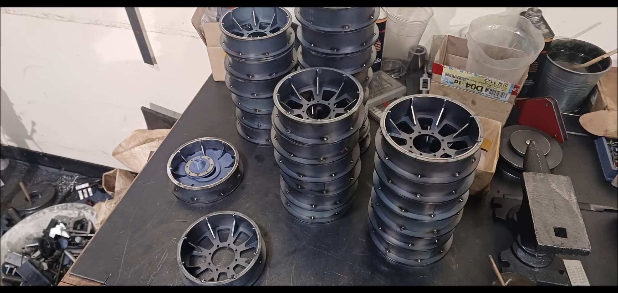
Spoke operation completed
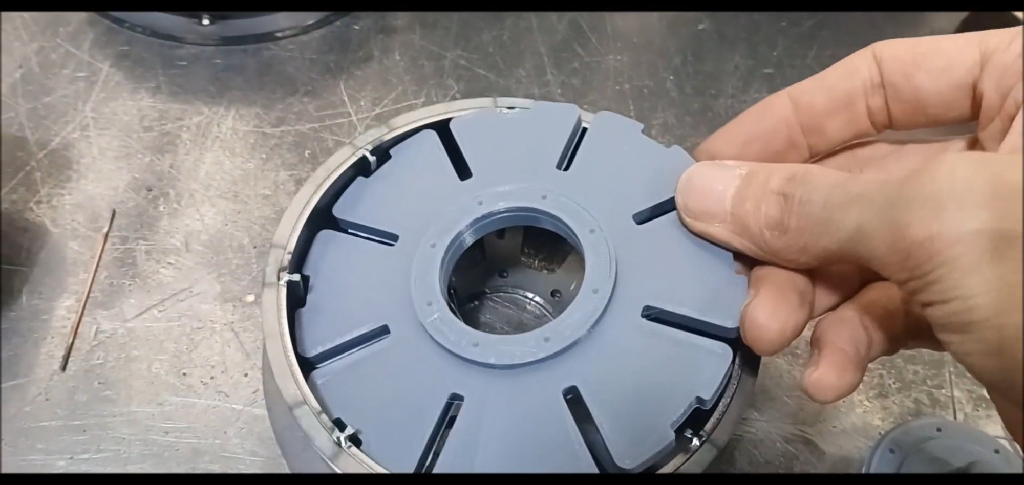
Create detailed parts with 3D printers
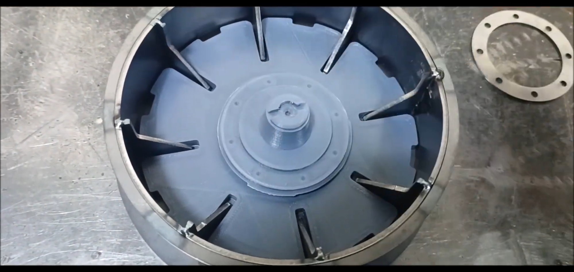
Identical drive wheel cover

Flanges to secure the same drive wheel cover
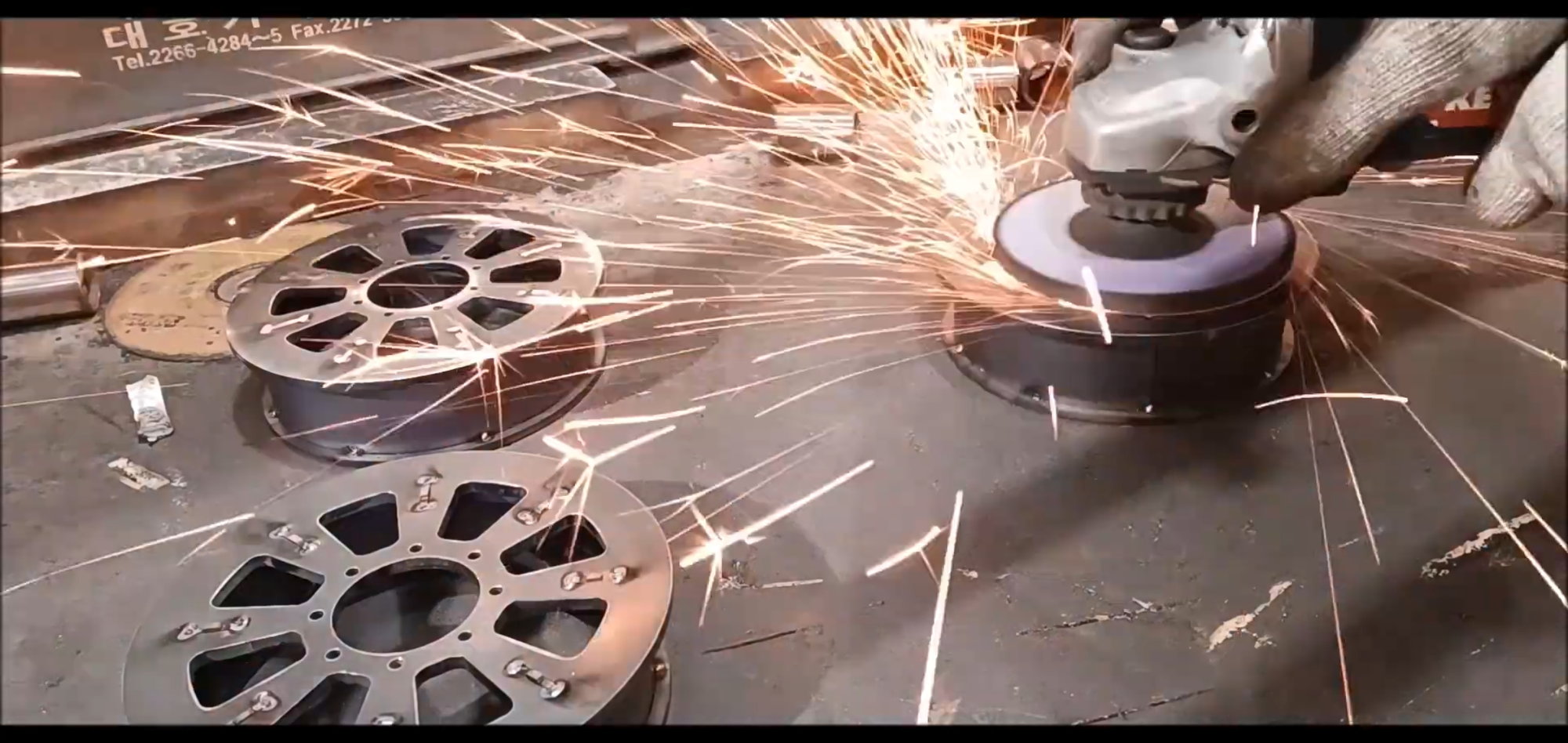
Remove the burrs on the rear of the bogie wheel with a hand grater.
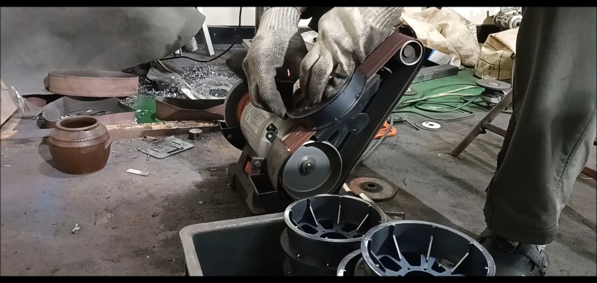
Finish with a flat grinder
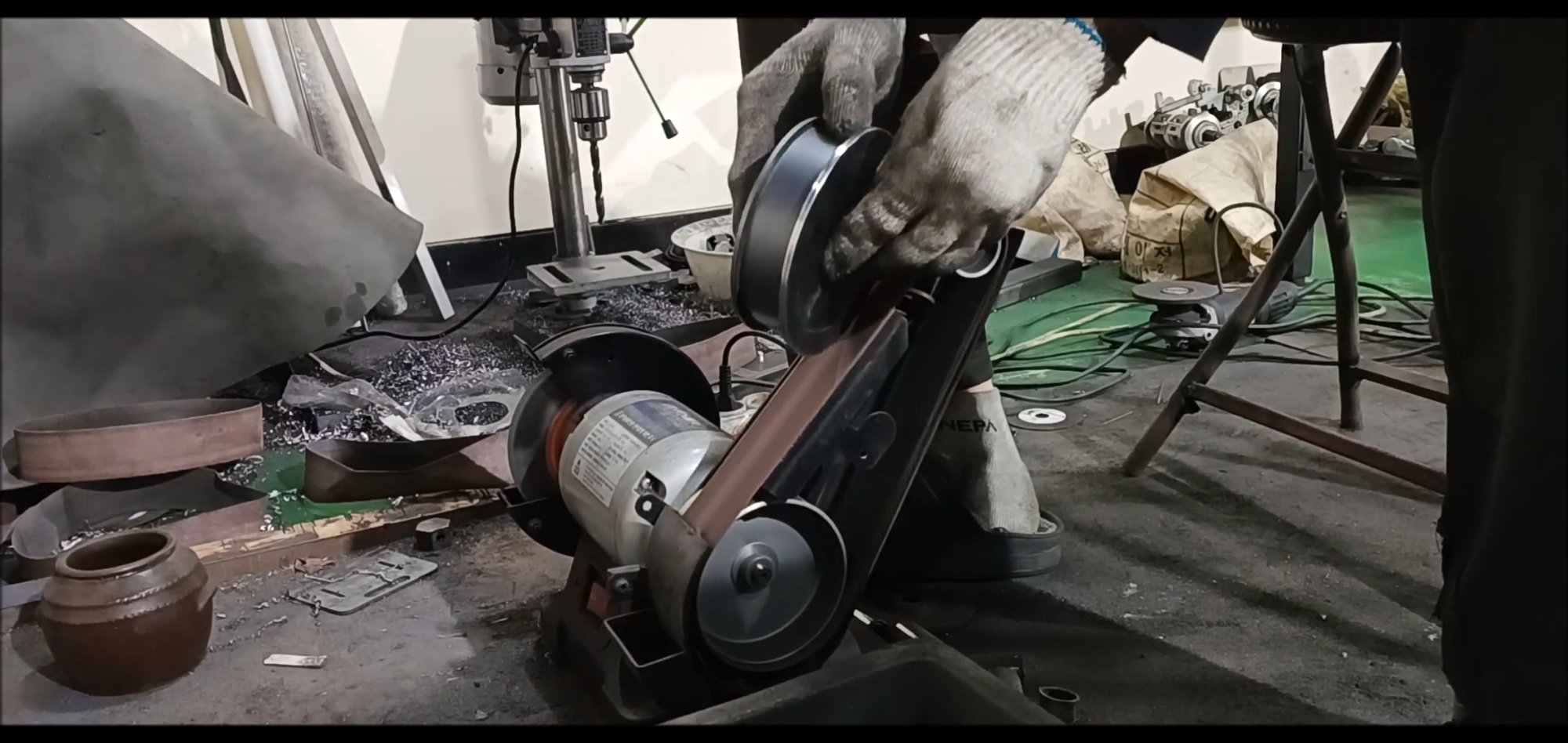
The sharp edges go smoothly, too.
Completing the grinder operation
Stand by for next action
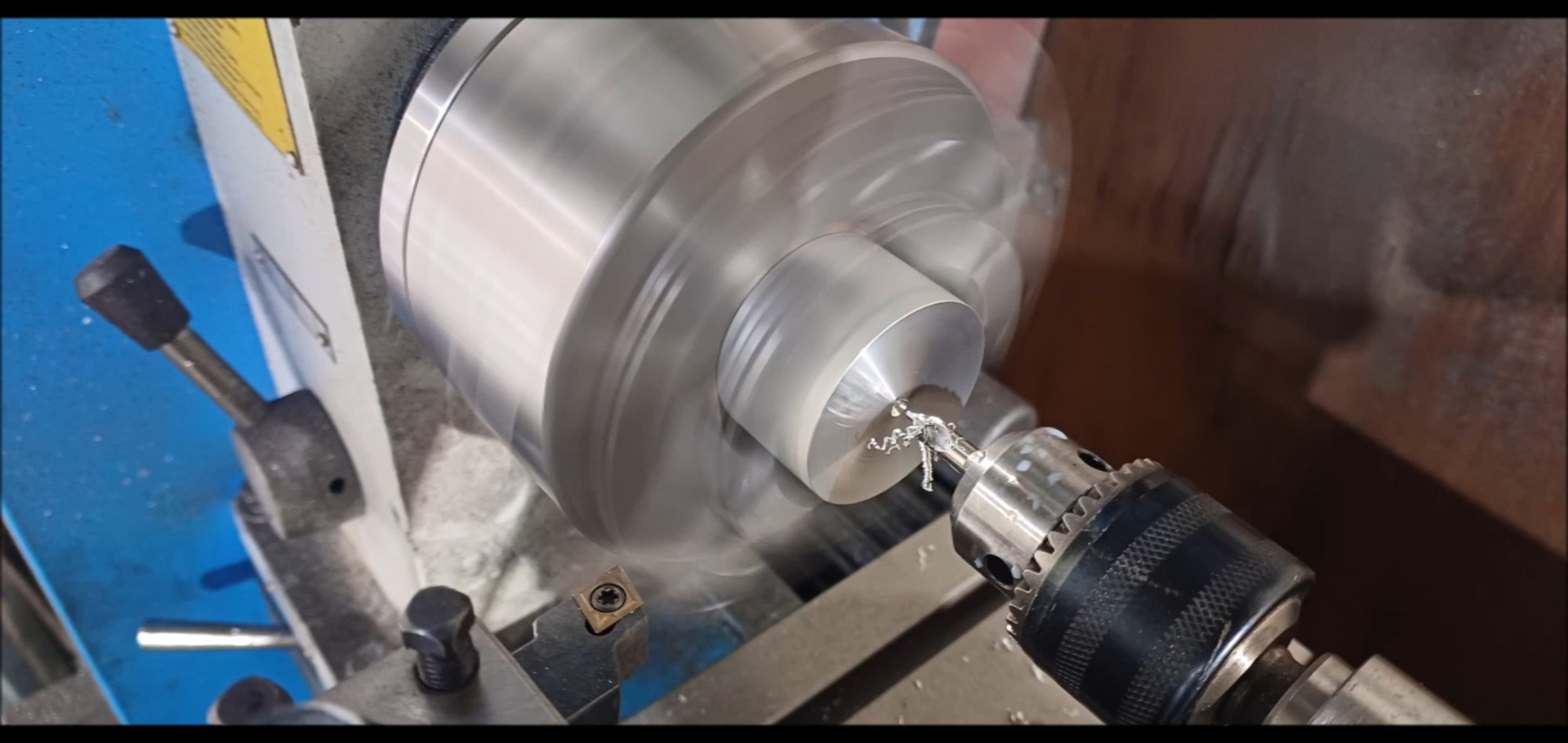
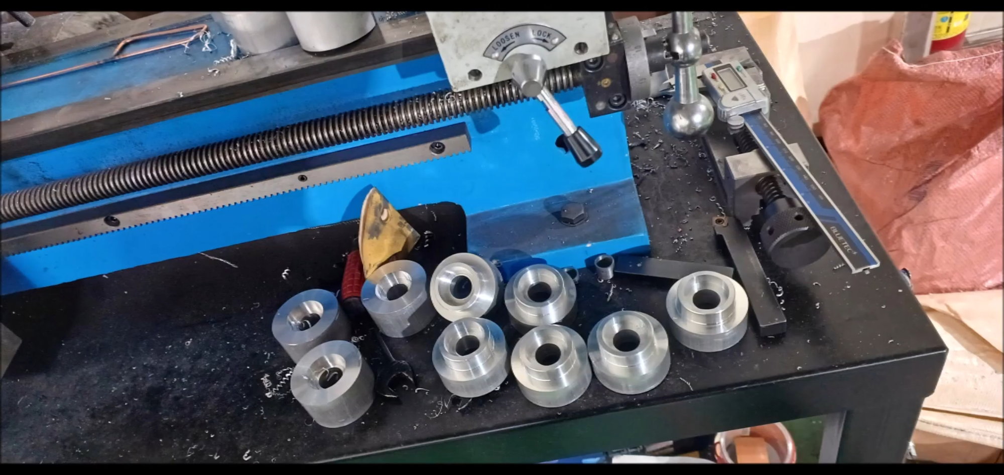
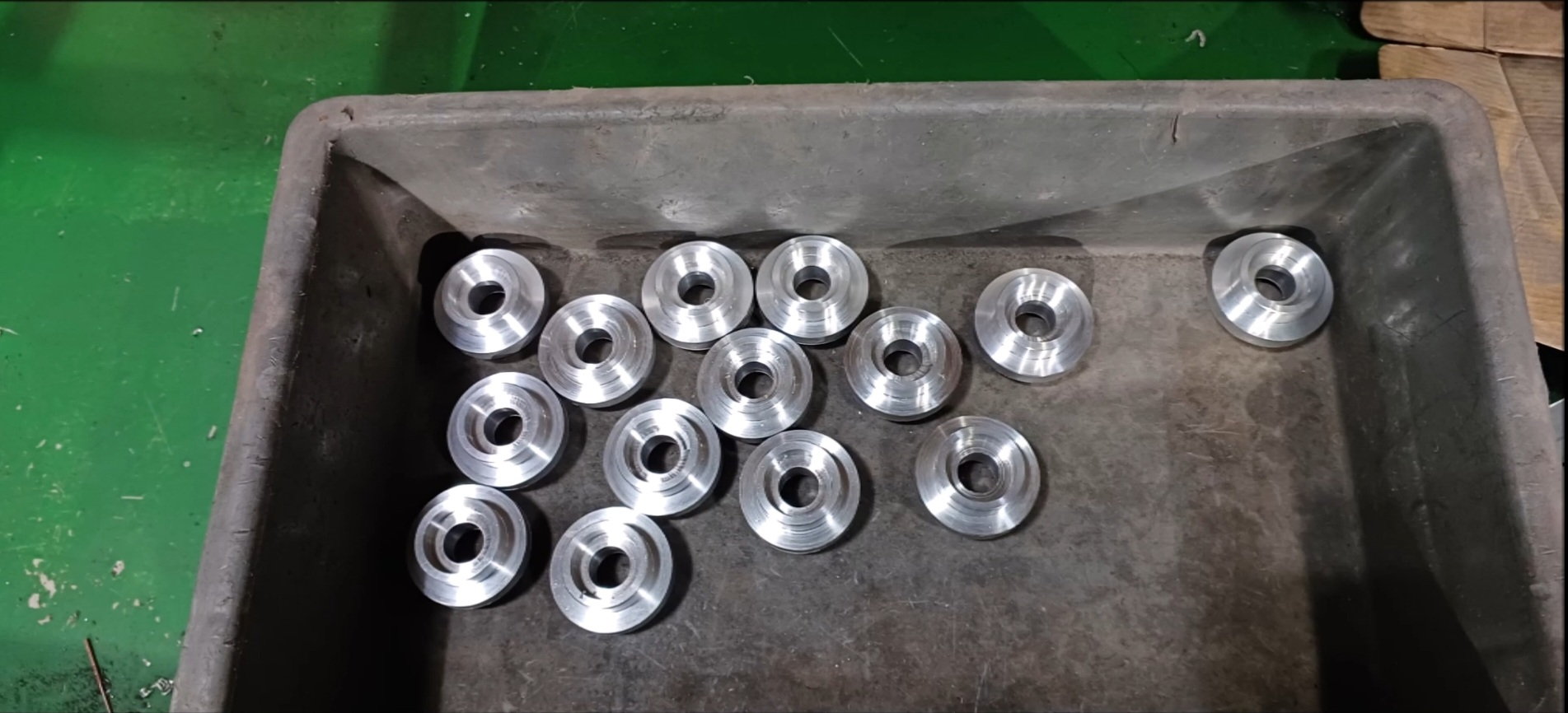
Connecting joint lathe processing
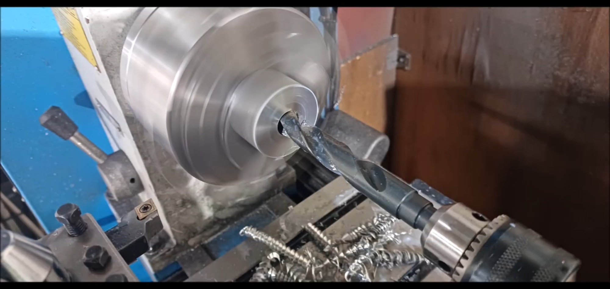
Smaller hole than bearing inner diameter
Hole work completed
Hole operation for bearing fixing
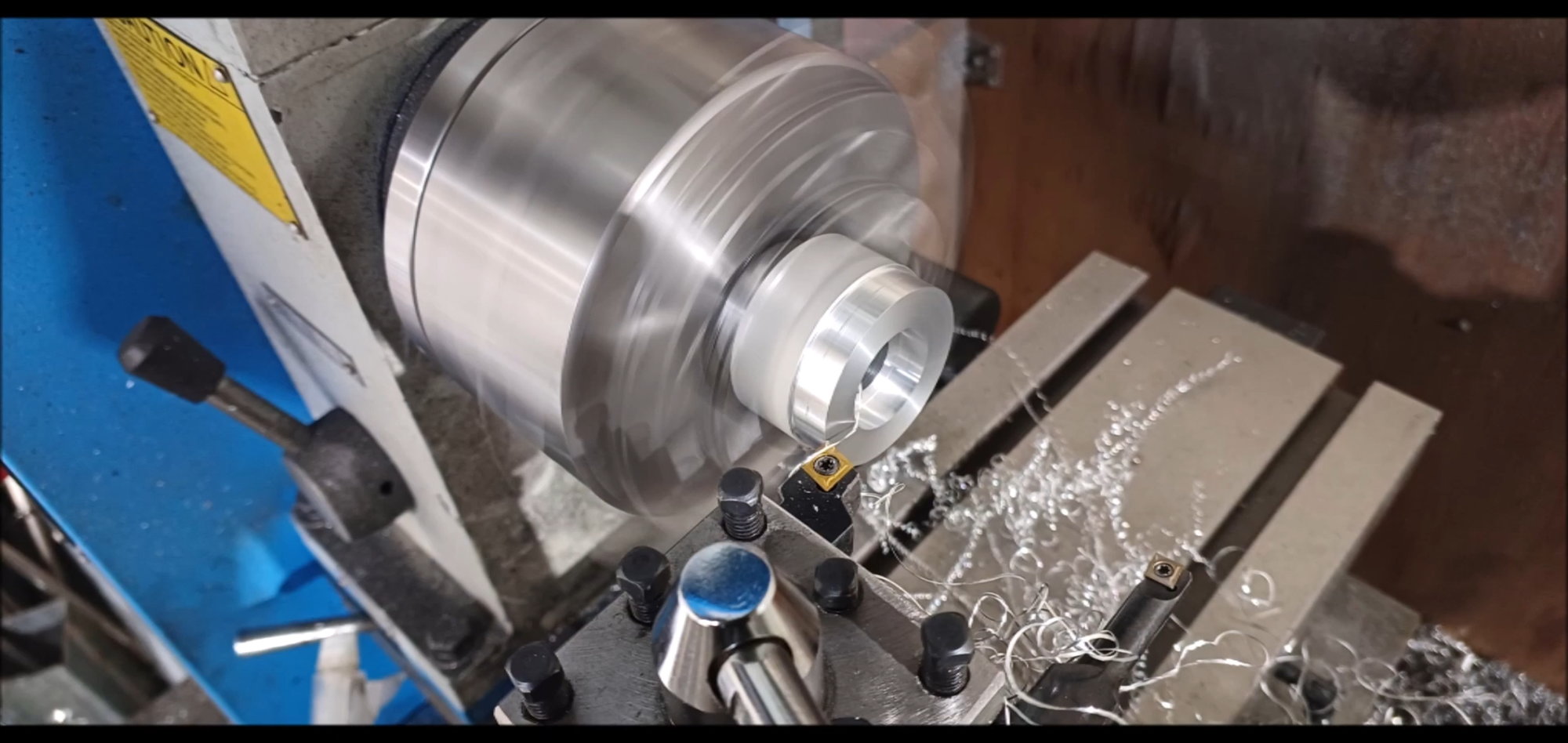
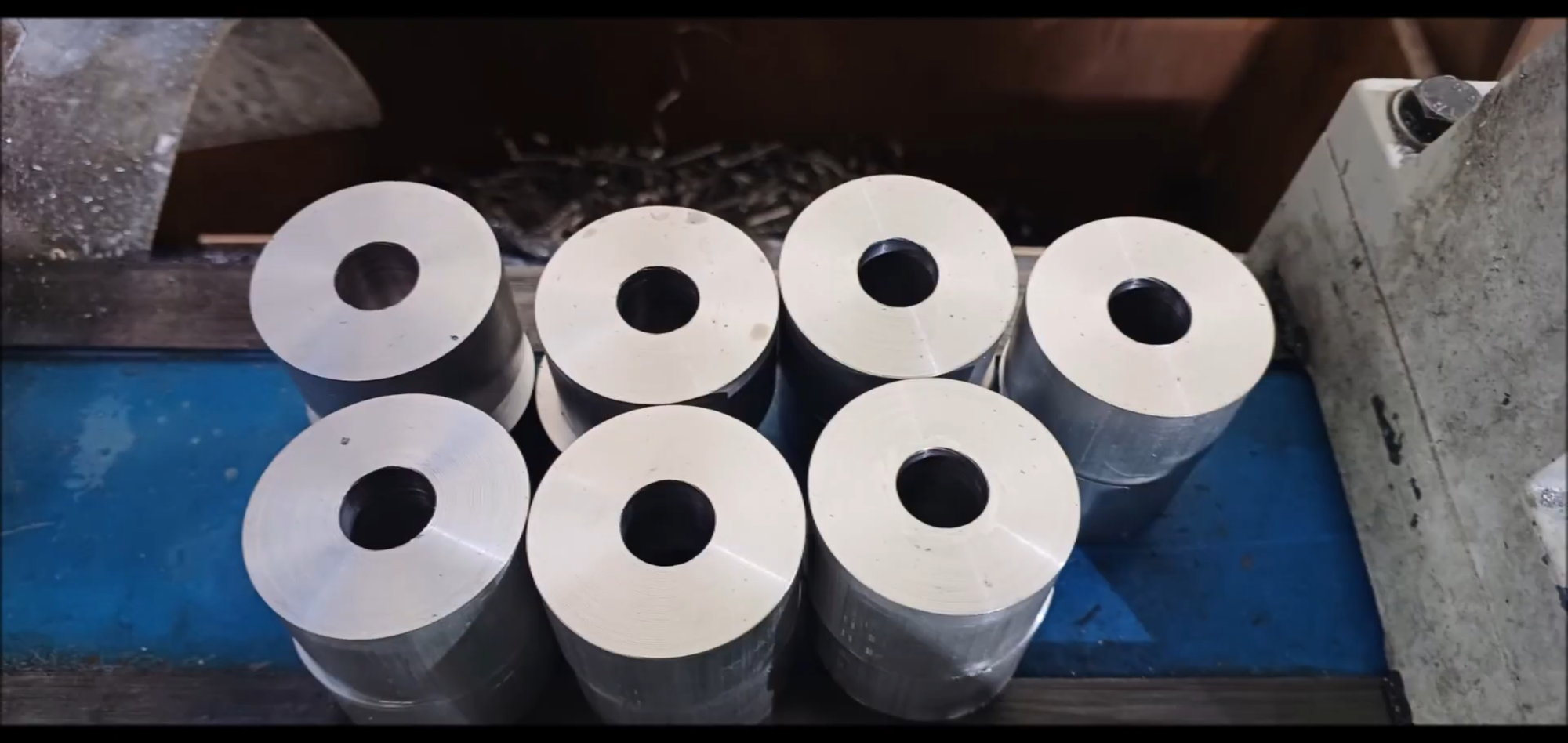
External diameter machining of joint to fit the internal diameter of the bogie wheel
Joint shape machining progress
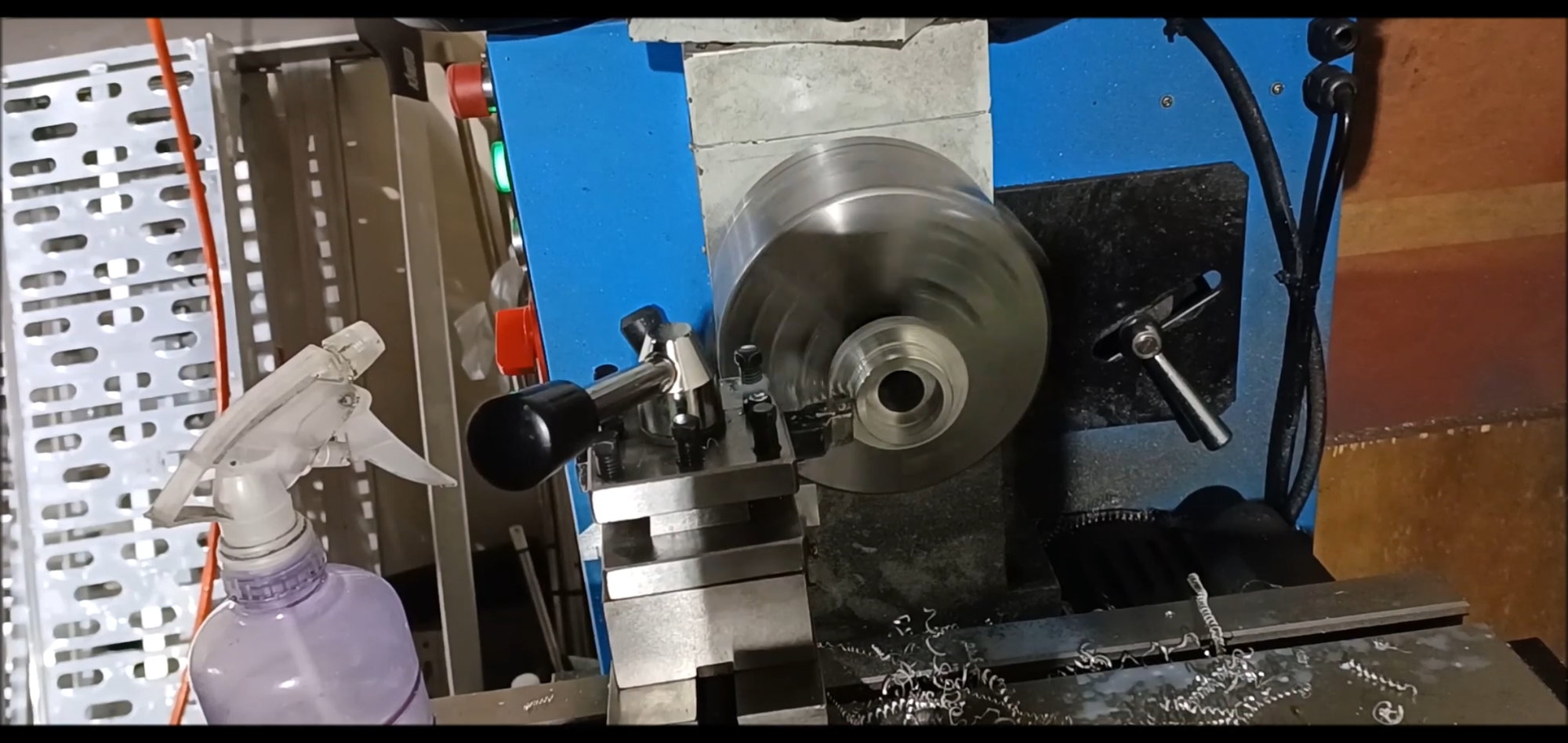
Shelf machine capacity is small, working repeatedly several times

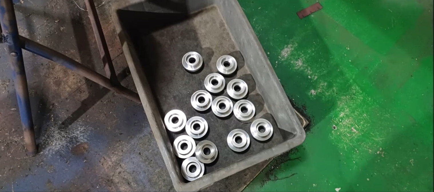
Joint shape machining completed
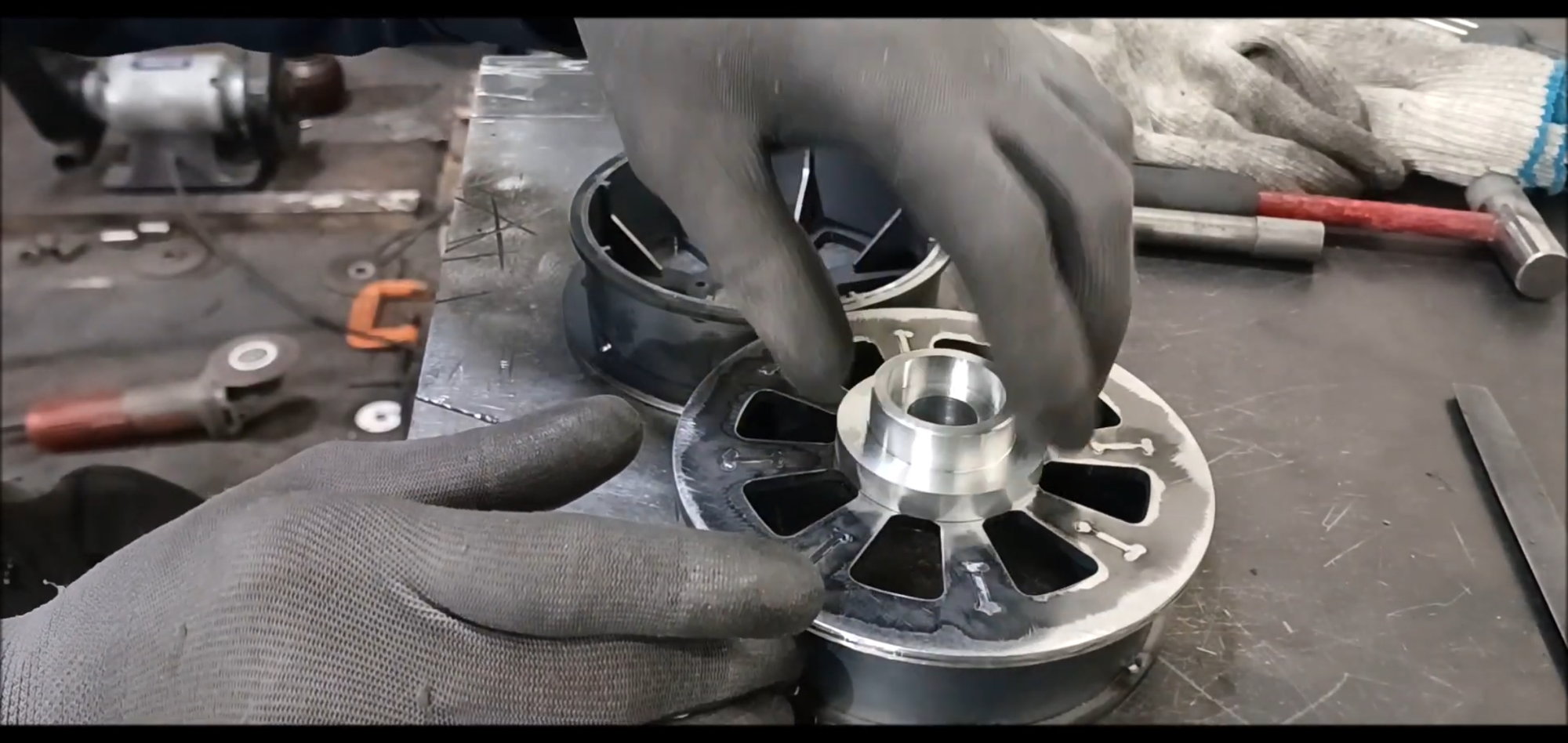
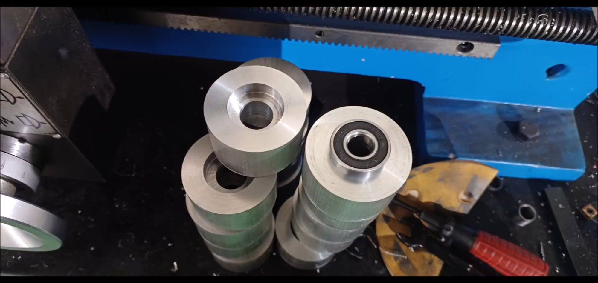
temporary assembly

Joint connection with two bogie wheels, bearing assembly example when installing
Check the clearance of the center guard of the track.
Prepare the flanges for hole work to match the bogie wheels.
Continued in the next episode
Regards,
Young
Bogie Wheel Work Continues Last Week
Install spokes on the viewing wheel
Spoke operation completed
Create detailed parts with 3D printers
Identical drive wheel cover
Flanges to secure the same drive wheel cover
Remove the burrs on the rear of the bogie wheel with a hand grater.
Finish with a flat grinder
The sharp edges go smoothly, too.
Completing the grinder operation
Stand by for next action
Connecting joint lathe processing
Smaller hole than bearing inner diameter
Hole work completed
Hole operation for bearing fixing
External diameter machining of joint to fit the internal diameter of the bogie wheel
Joint shape machining progress
Shelf machine capacity is small, working repeatedly several times
Joint shape machining completed
temporary assembly
Joint connection with two bogie wheels, bearing assembly example when installing
Check the clearance of the center guard of the track.
Prepare the flanges for hole work to match the bogie wheels.
Continued in the next episode
The following users liked this post:
tankme (03-19-2023)
03-27-2023, 10:24 PM
#30
Thread Starter
This episode was continued in the last episode with bogie wheel work.
The thickness of the bogie wheel of the 2023 K2 Black Panther (ic2504) is 1 mm thicker than that of 2022, and the shaft cover also runs with the bogie wheel.
Regards,
Young
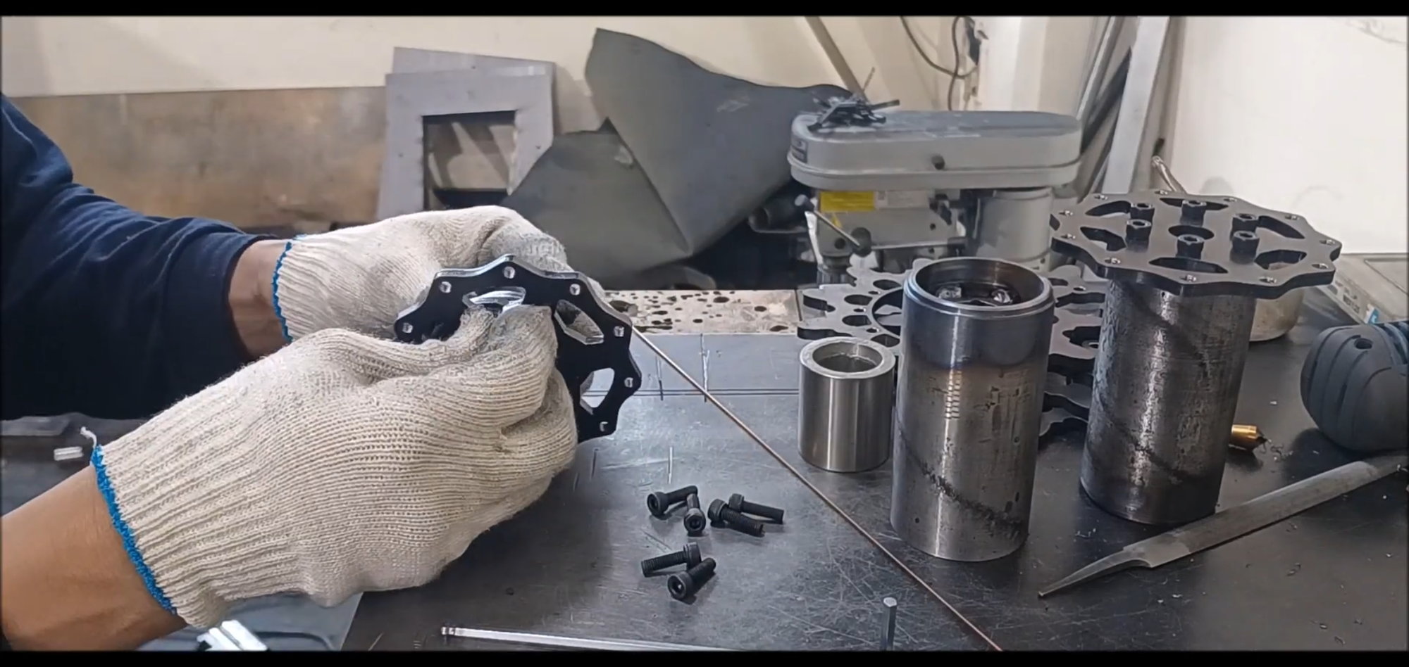
A bogie wheel connection hub created in the last episode.
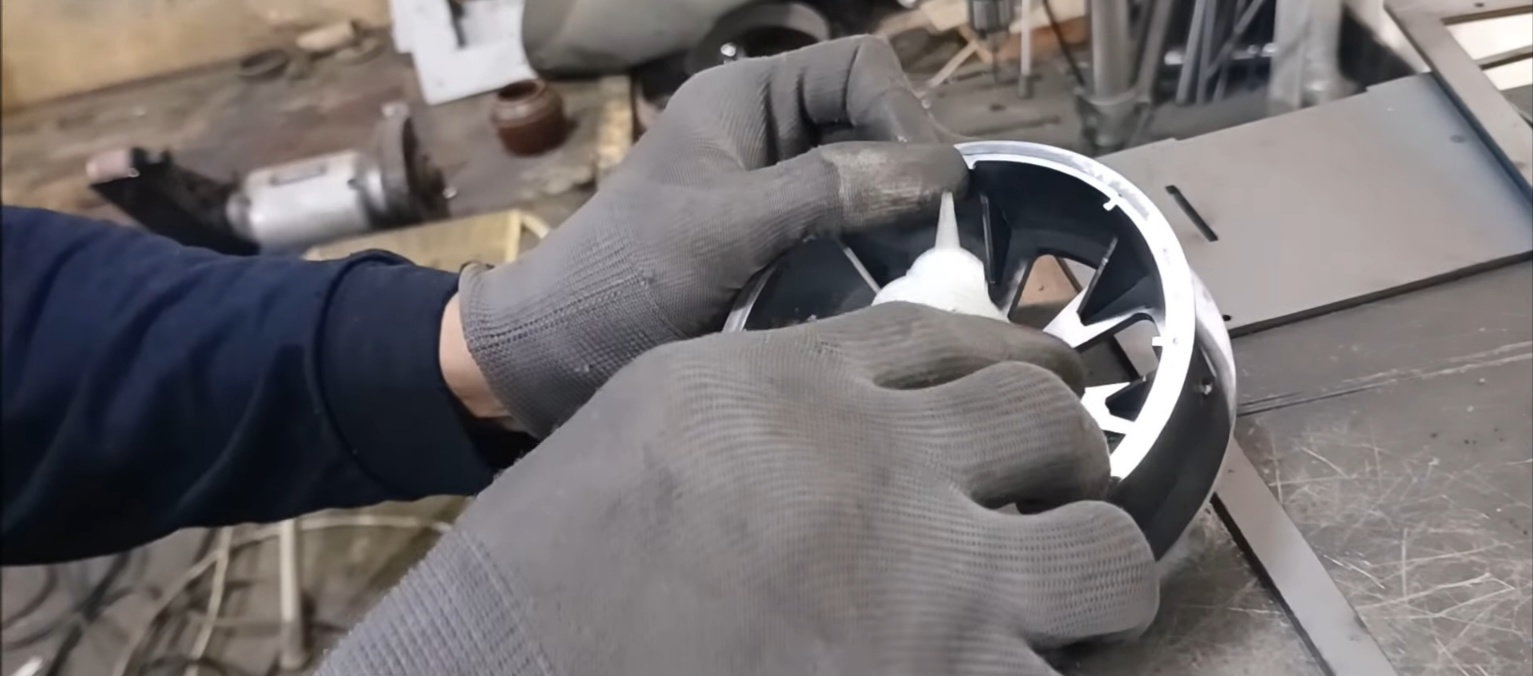
Temporary fix the bogie wheel and hub with instantaneous adhesive to install bolt holes in the flange of the bogie wheel connection hub.
Press by hand for a while while the instantaneous adhesive hardens.
Temporary connection of the viewing wheel to the hub
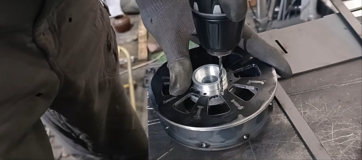
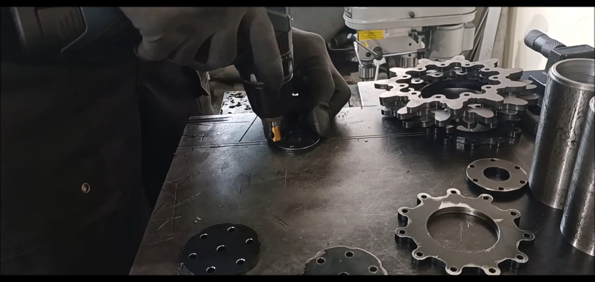
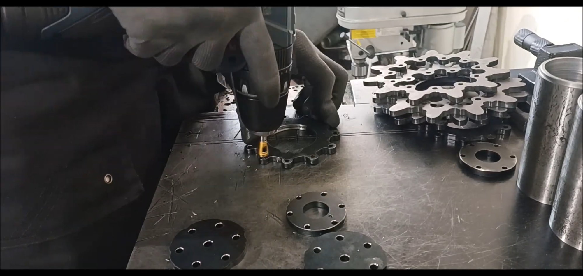
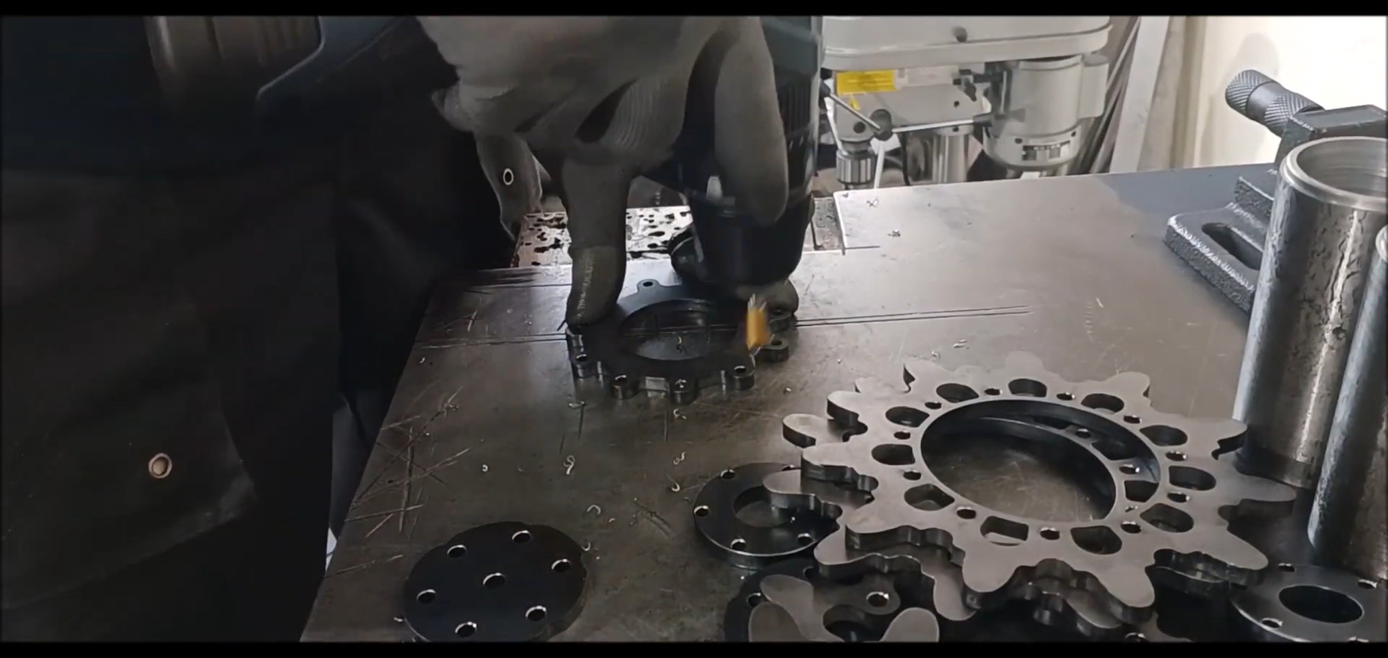
Do the reference work on the flange of the hub to drill holes.
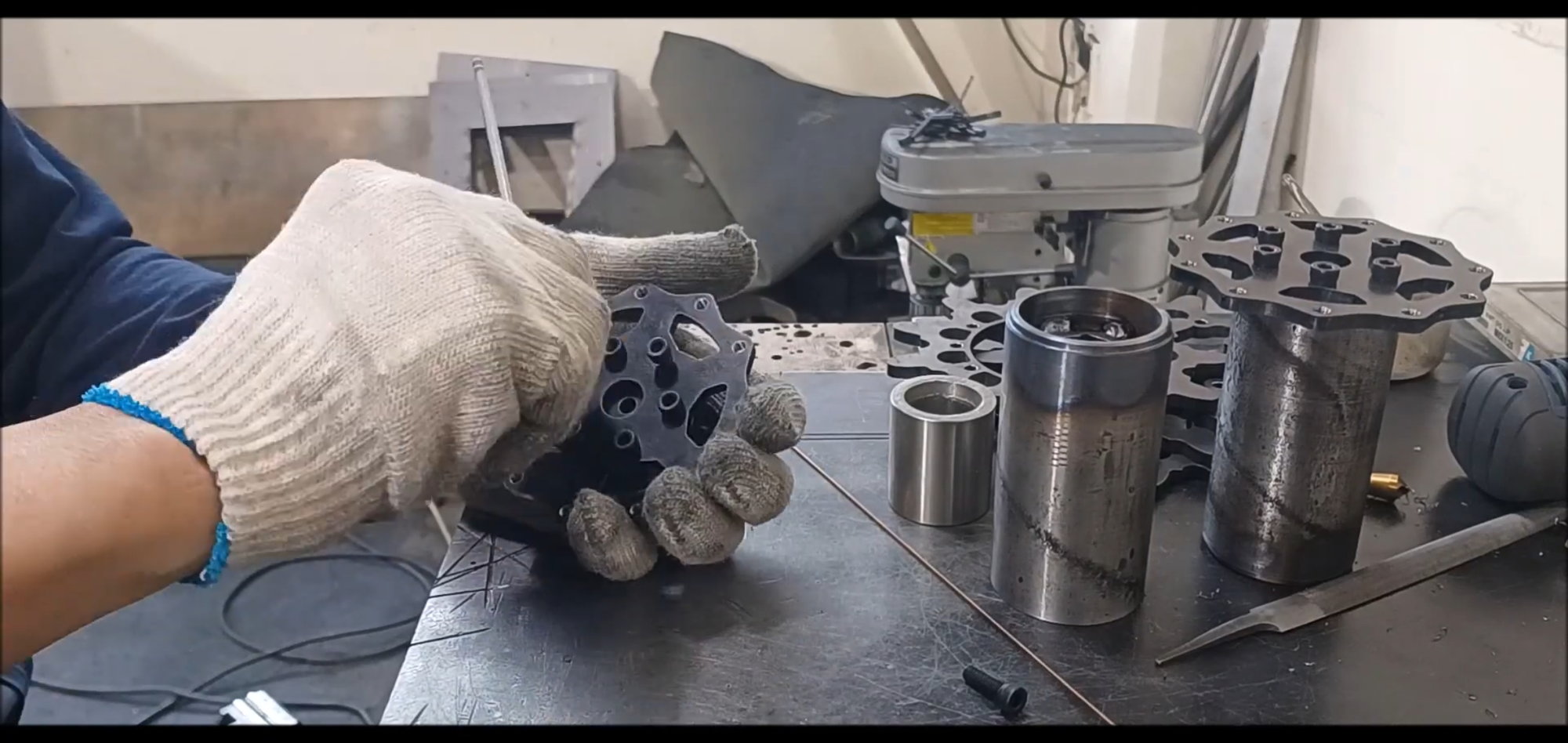
Bogie wheel connection hub with reference work done
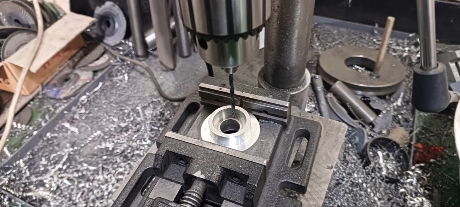
ull-fledged hole work. Use a 3.3 mm drill to allow 3 mm bolts to pass through the hole.
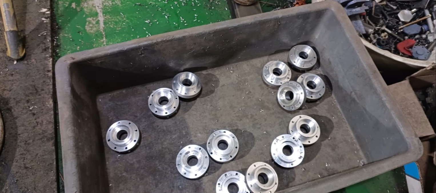
Bogie wheel connection hub with hole work done
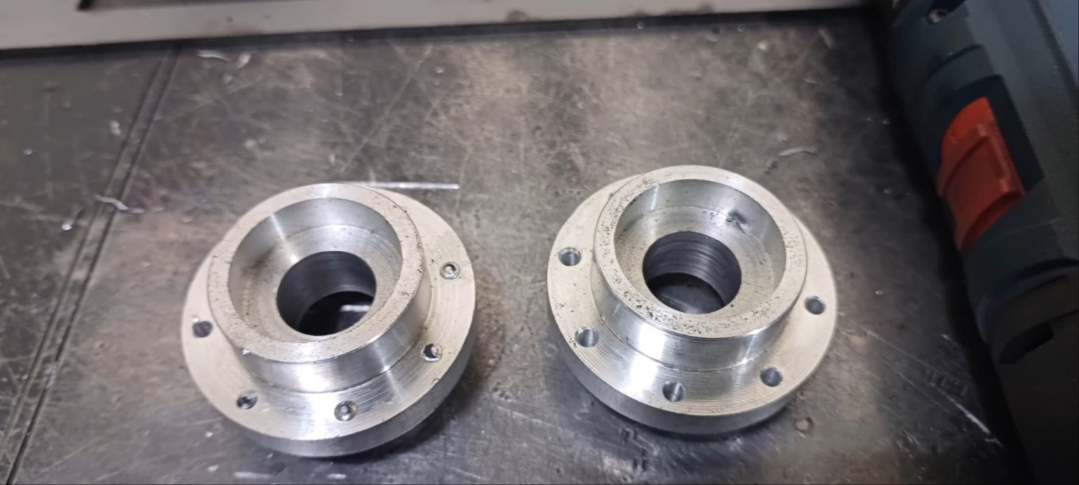
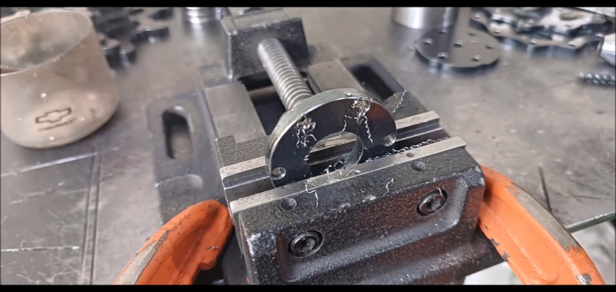
Burr must be removed from the flange hole and bearing seating
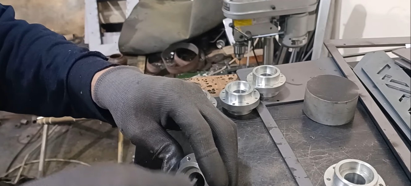
Since it is made of aluminum, chamfer work or burr removal is simply done with a cutter, not with a shelf machine
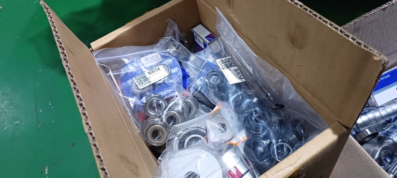
Bearings prepared for the next process
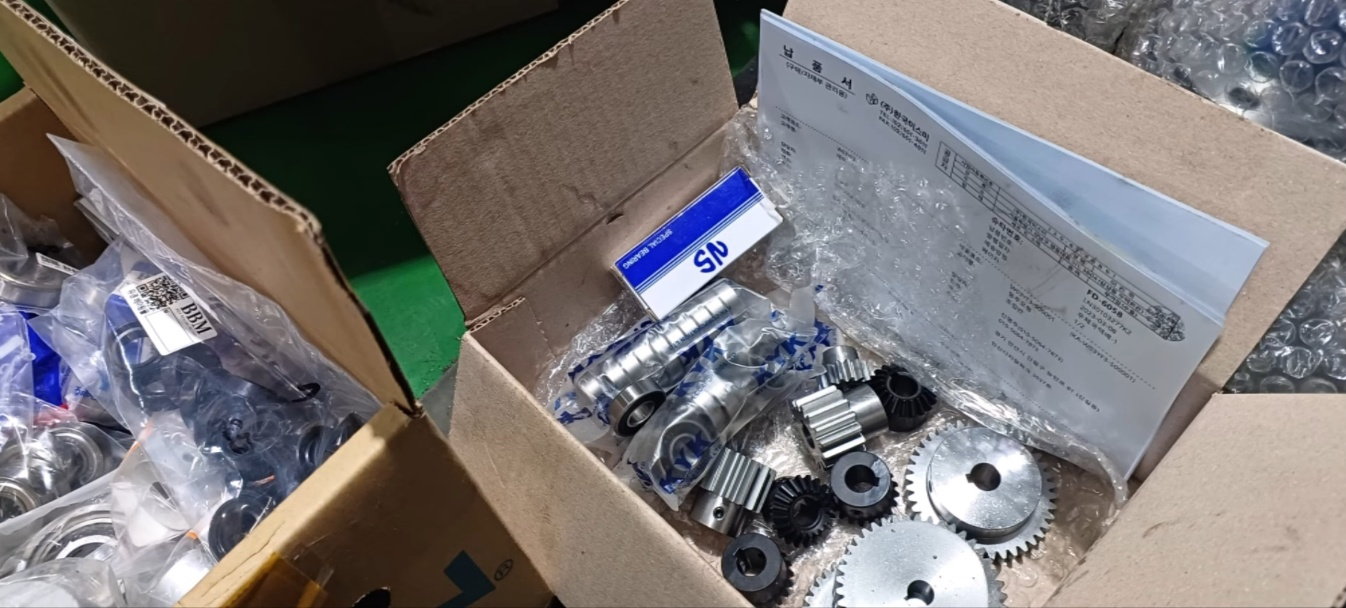
Retainer seal and gears prepared for the next process
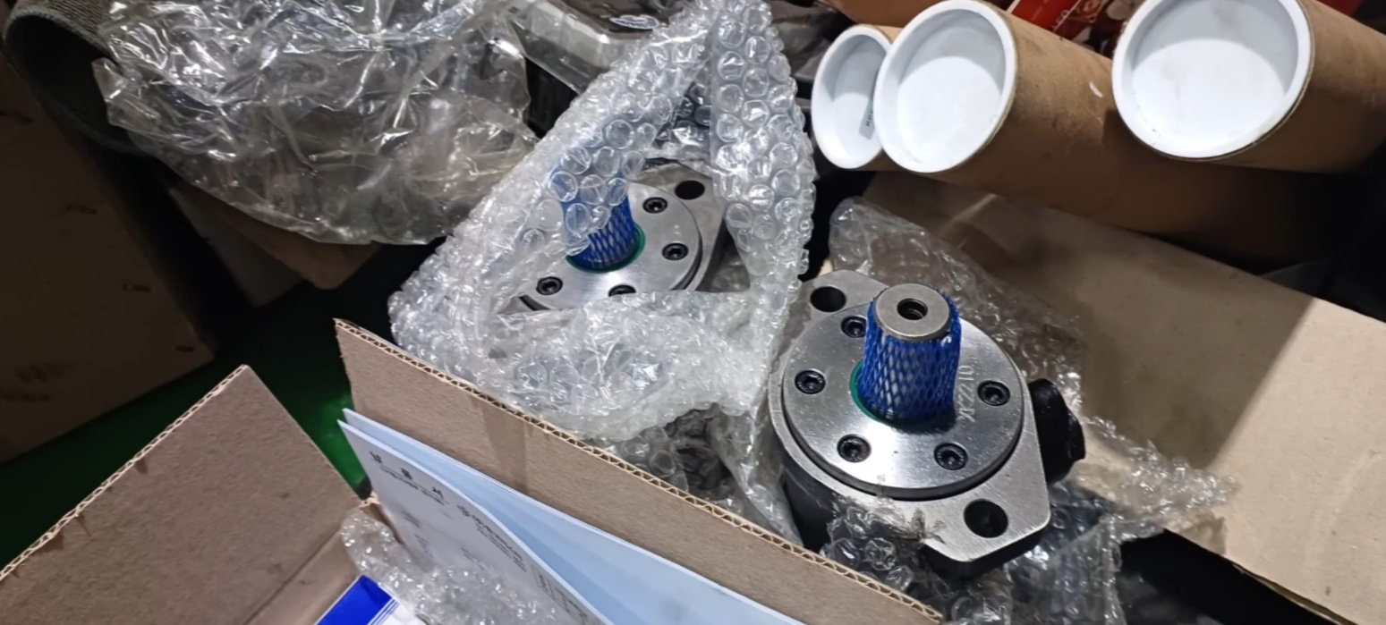
Hydraulic drive motor
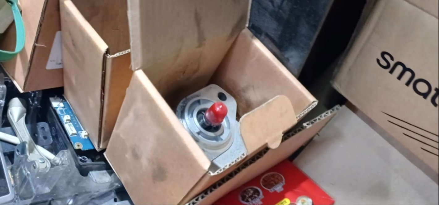
Hydraulic drive pump
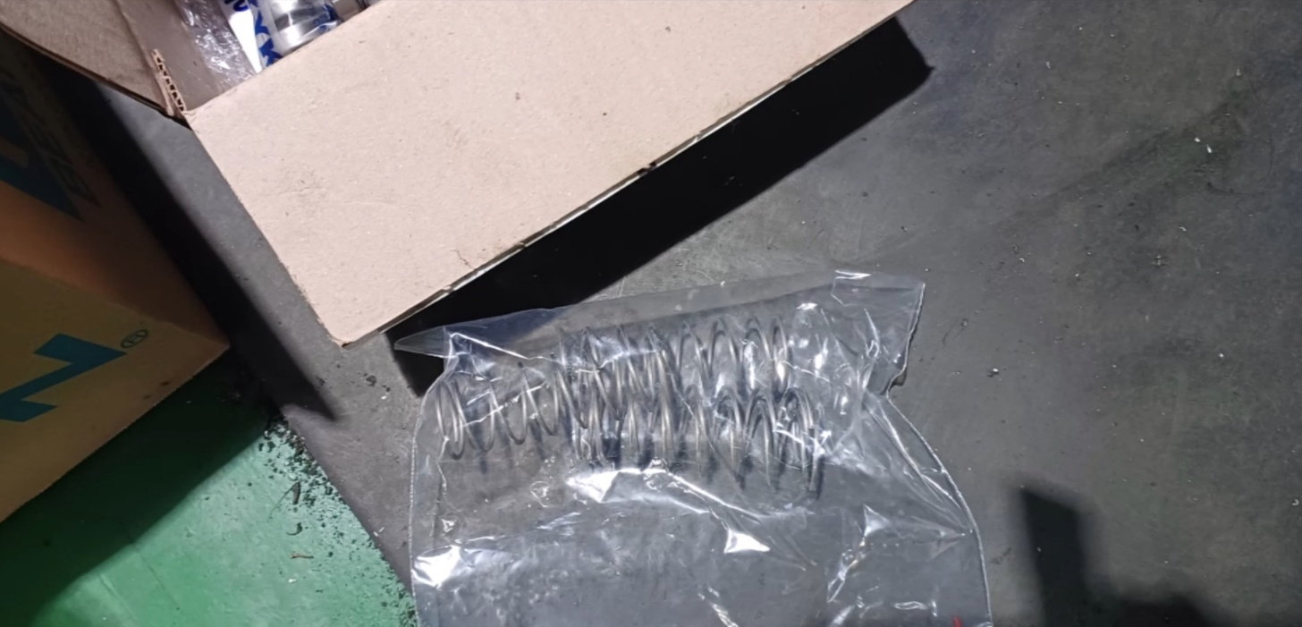
A spring for neutral gears
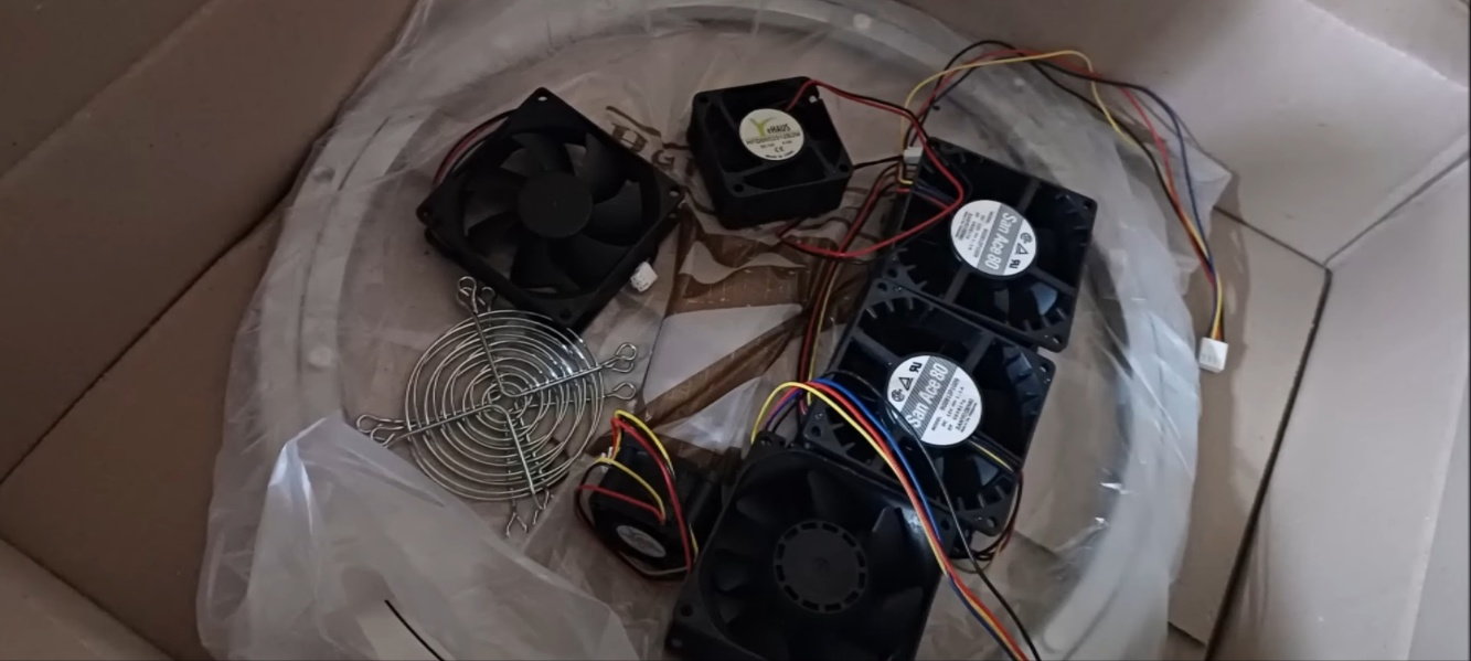
Turret gear and cooling fans
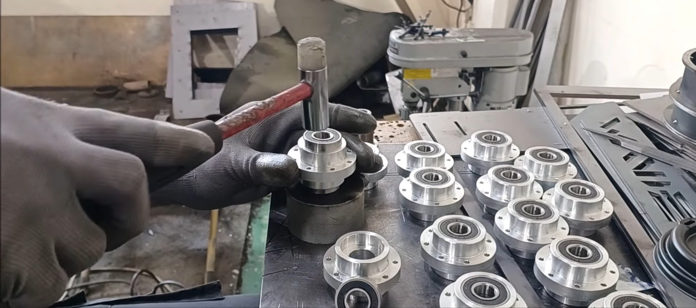
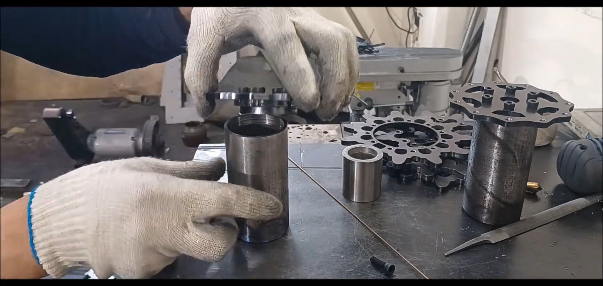
Insert bearing into bogie wheel connection hub
lattening the bearing insertion operation in the bogie wheel connection hub
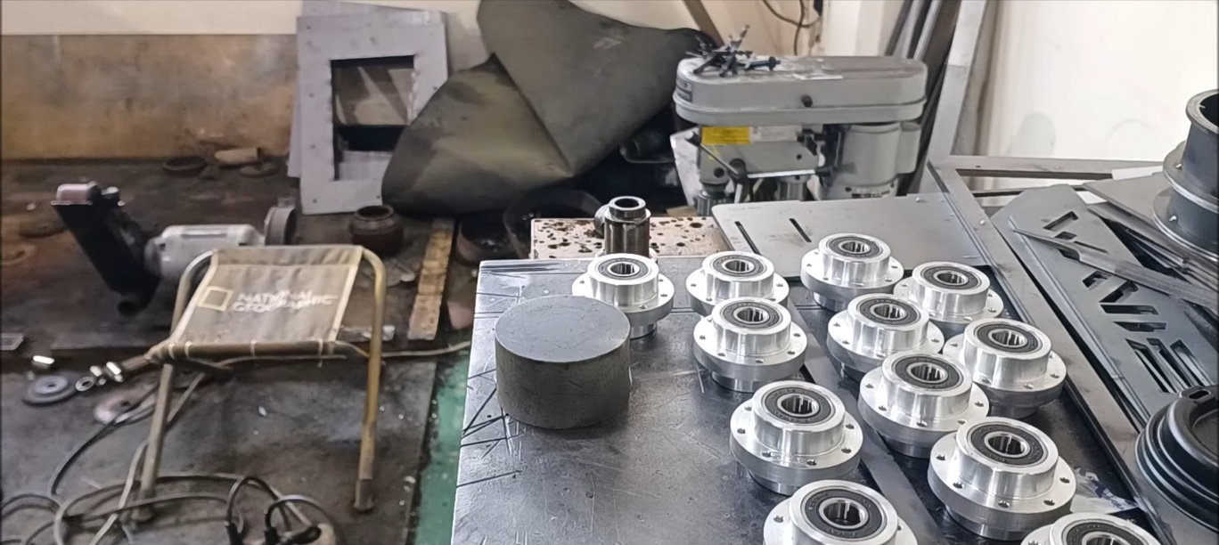
Bearing inserted bogie wheel connection hub
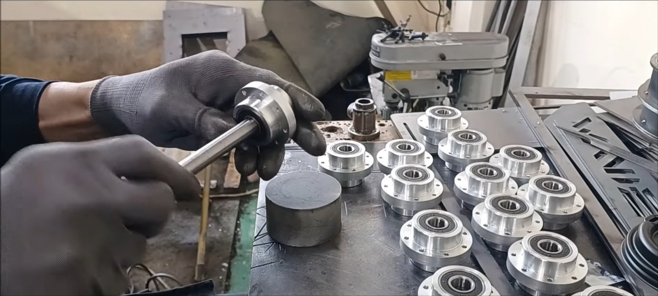
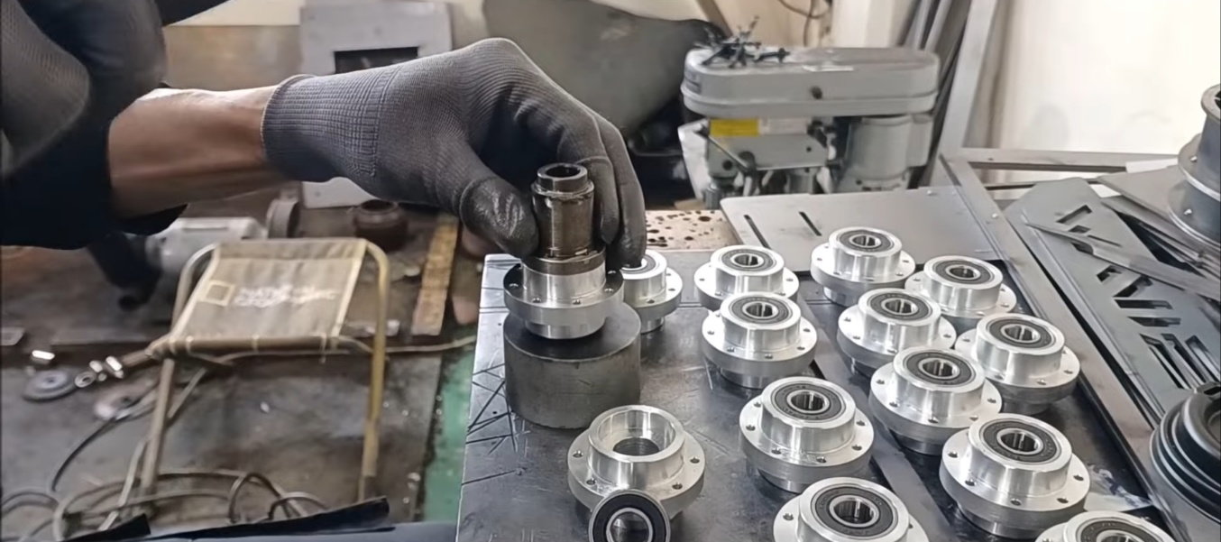
Bearing Shaft Insertion Test
Sample assembly for bogie wheel centering inspection
mporary tightening of bolts and nuts for sample assembly for bogie wheel centering inspection
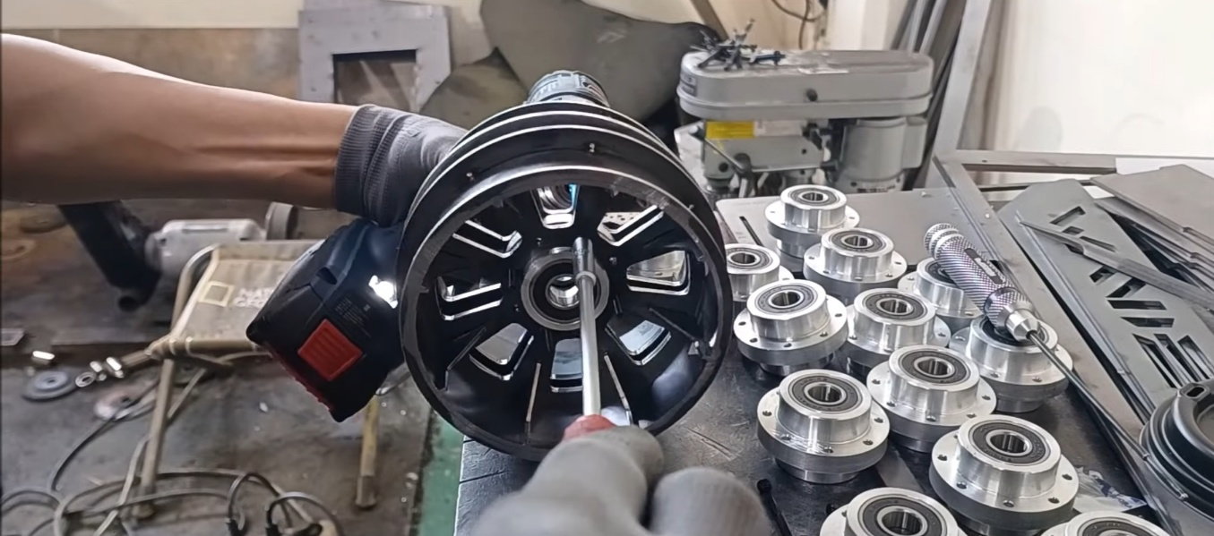
The bogie wheel was combined with the shaft and rotated to confirm that it worked very well
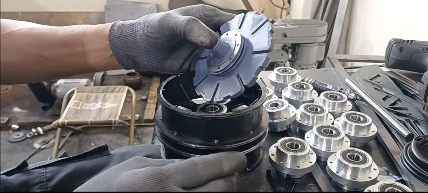
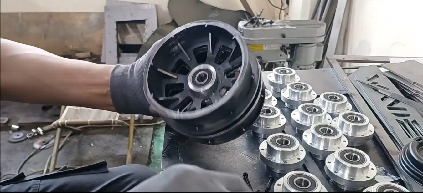
3D sculptures and shaft covers to be used on the inside of the bogie wheel
In the next episode, there will be a drive wheel operation
In the next episode......
The thickness of the bogie wheel of the 2023 K2 Black Panther (ic2504) is 1 mm thicker than that of 2022, and the shaft cover also runs with the bogie wheel.
Regards,
Young
A bogie wheel connection hub created in the last episode.
Temporary fix the bogie wheel and hub with instantaneous adhesive to install bolt holes in the flange of the bogie wheel connection hub.
Press by hand for a while while the instantaneous adhesive hardens.
Temporary connection of the viewing wheel to the hub
Do the reference work on the flange of the hub to drill holes.
Bogie wheel connection hub with reference work done
ull-fledged hole work. Use a 3.3 mm drill to allow 3 mm bolts to pass through the hole.
Bogie wheel connection hub with hole work done
Burr must be removed from the flange hole and bearing seating
Since it is made of aluminum, chamfer work or burr removal is simply done with a cutter, not with a shelf machine
Bearings prepared for the next process
Retainer seal and gears prepared for the next process
Hydraulic drive motor
Hydraulic drive pump
A spring for neutral gears
Turret gear and cooling fans
Insert bearing into bogie wheel connection hub
lattening the bearing insertion operation in the bogie wheel connection hub
Bearing inserted bogie wheel connection hub
Bearing Shaft Insertion Test
Sample assembly for bogie wheel centering inspection
mporary tightening of bolts and nuts for sample assembly for bogie wheel centering inspection
The bogie wheel was combined with the shaft and rotated to confirm that it worked very well
3D sculptures and shaft covers to be used on the inside of the bogie wheel
In the next episode, there will be a drive wheel operation
In the next episode......
Last edited by PE YOUNG; 03-27-2023 at 10:28 PM.
 04-01-2023, 02:09 AM
#34
Thread Starter
For production inquiries, write to Mr.Shin.
Please feel free to inquire.
Below is his email address.
[email protected]
Please feel free to inquire.
Below is his email address.
[email protected]
Last edited by PE YOUNG; 04-01-2023 at 02:18 AM.
04-01-2023, 02:13 AM
#35
Thread Starter
04-02-2023, 09:16 PM
#36
Thread Starter
From mid-April, K2's work speed seems to be accelerating.
This is because another project is currently underway first and it needs to be finished.
Today's episode
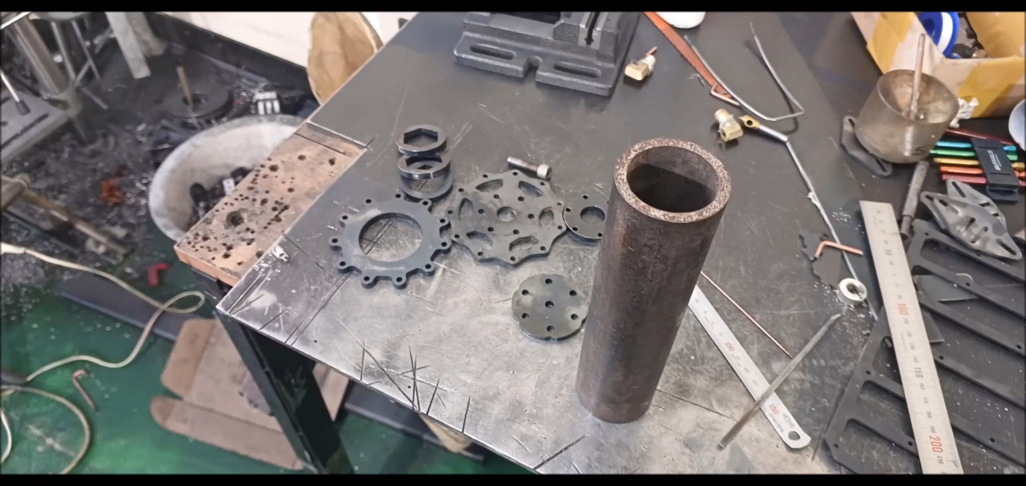
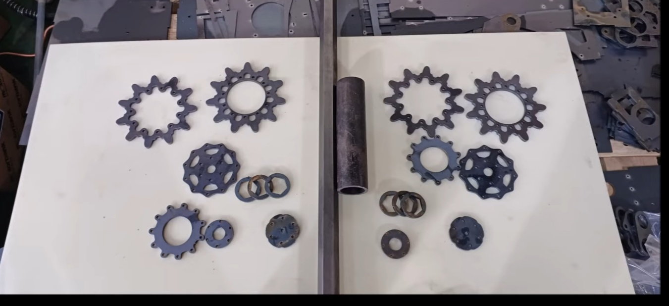
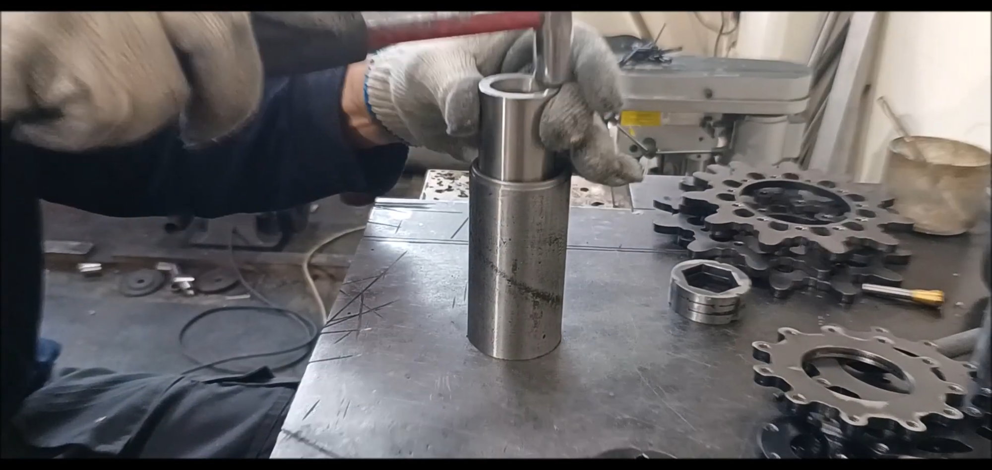
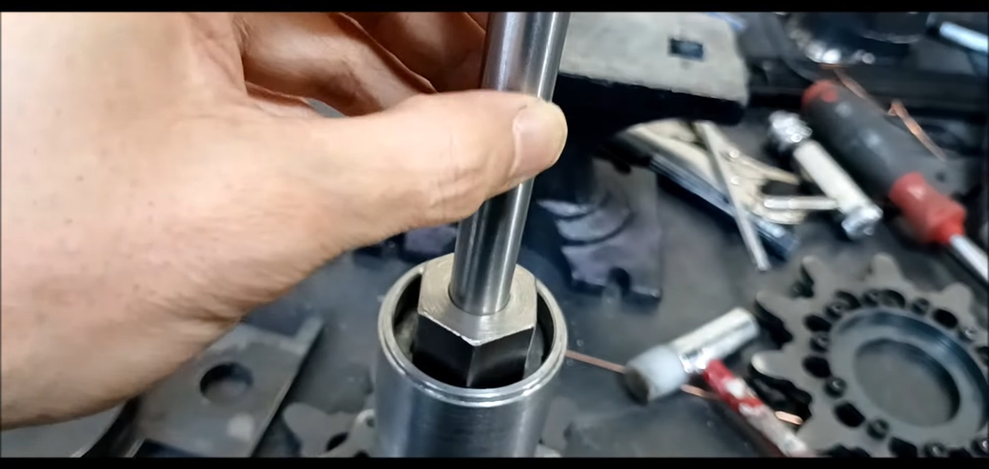
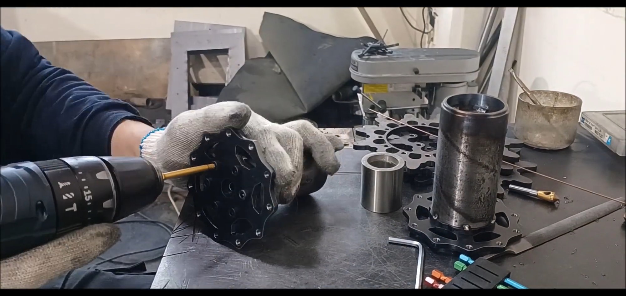
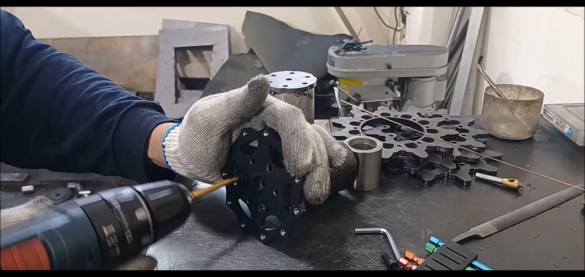
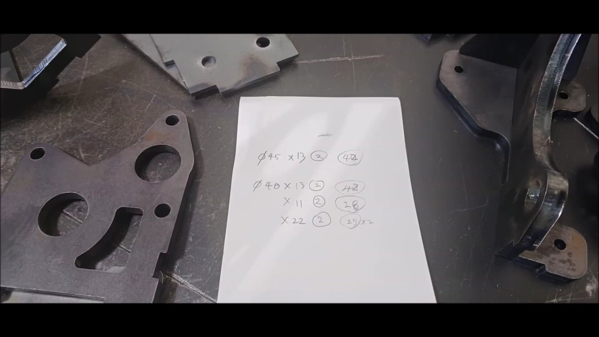
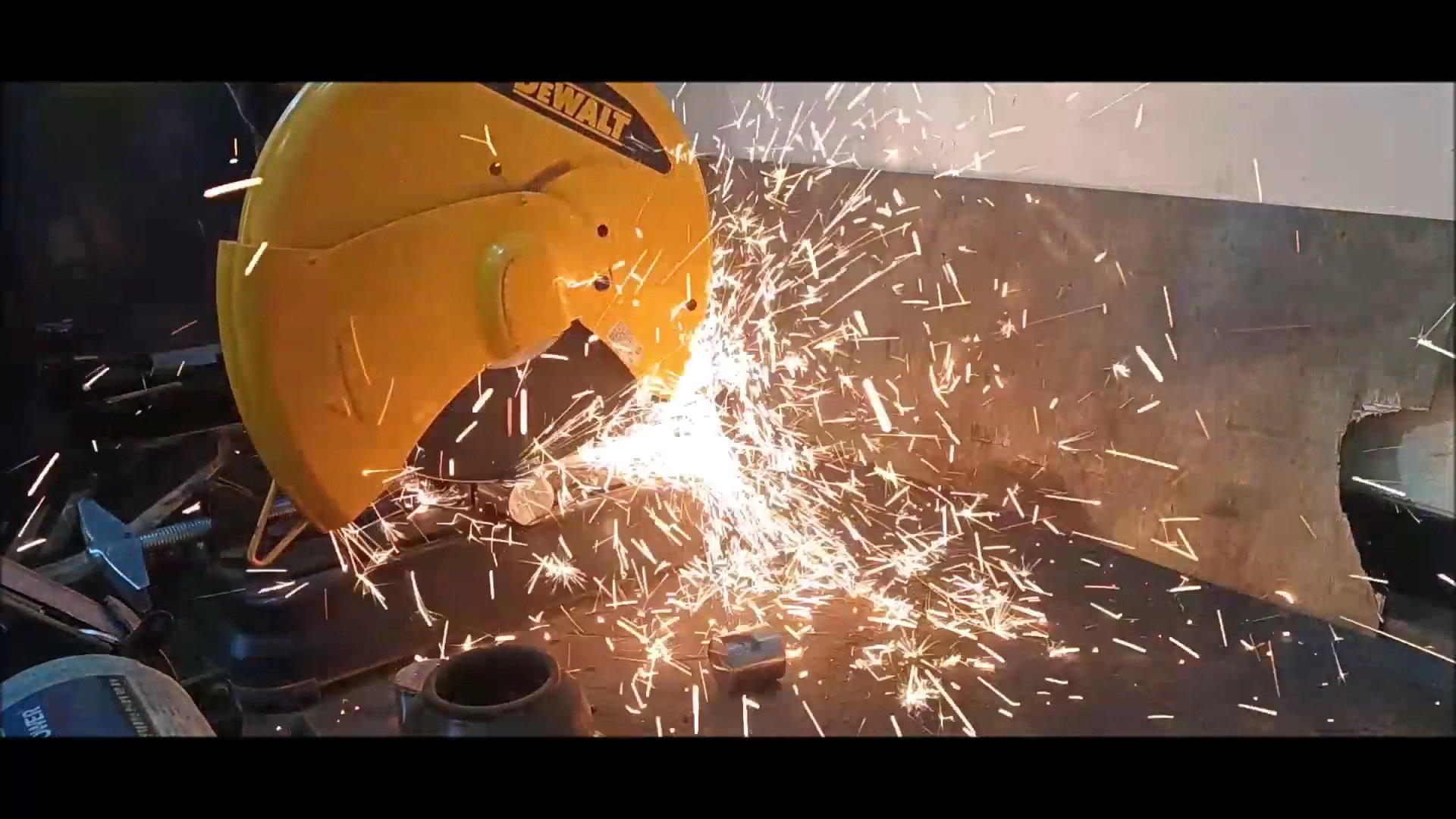
The material required for drive wheel fabrication is mod steel. Prepare two seamless pipes for laser cutting and drive wheel shafts.
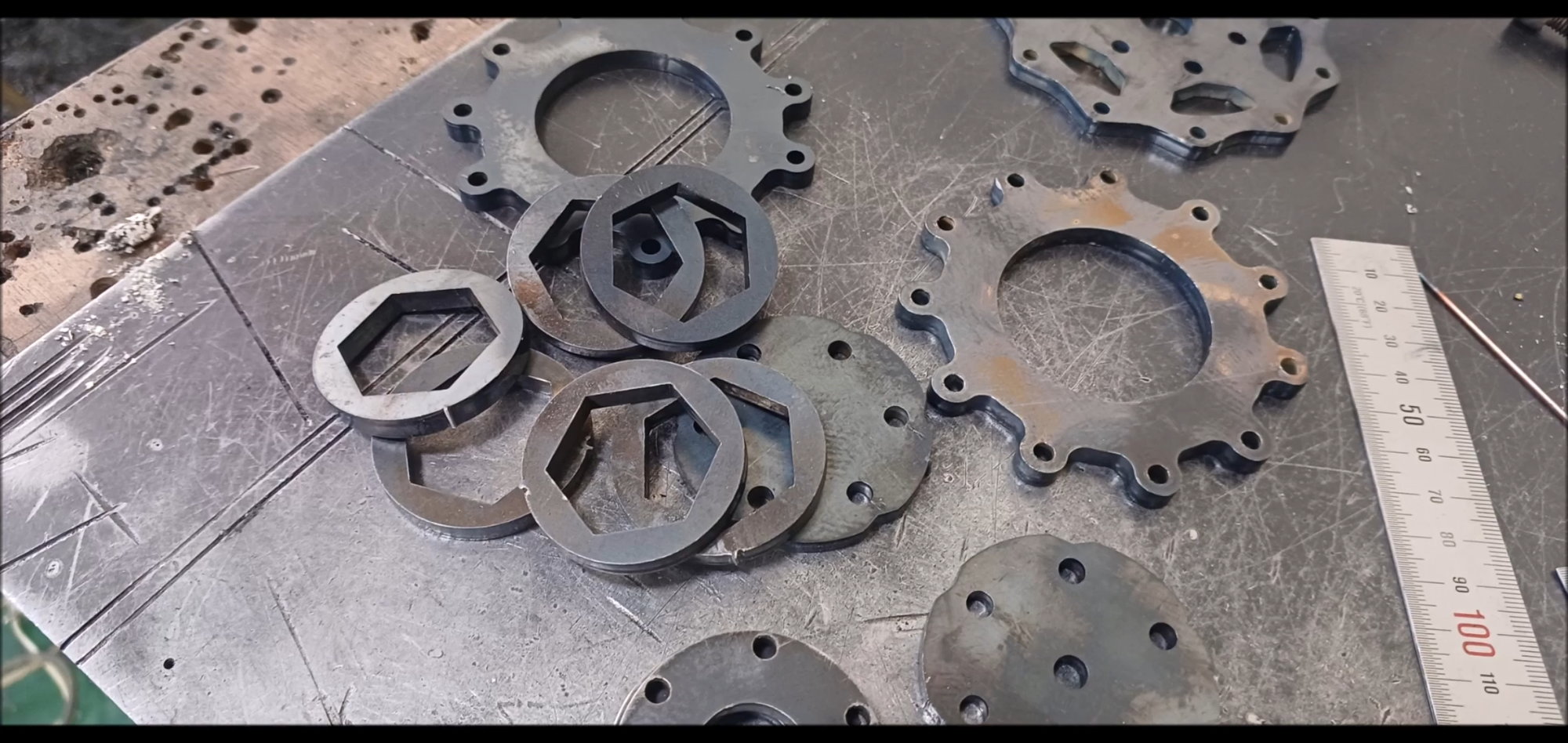
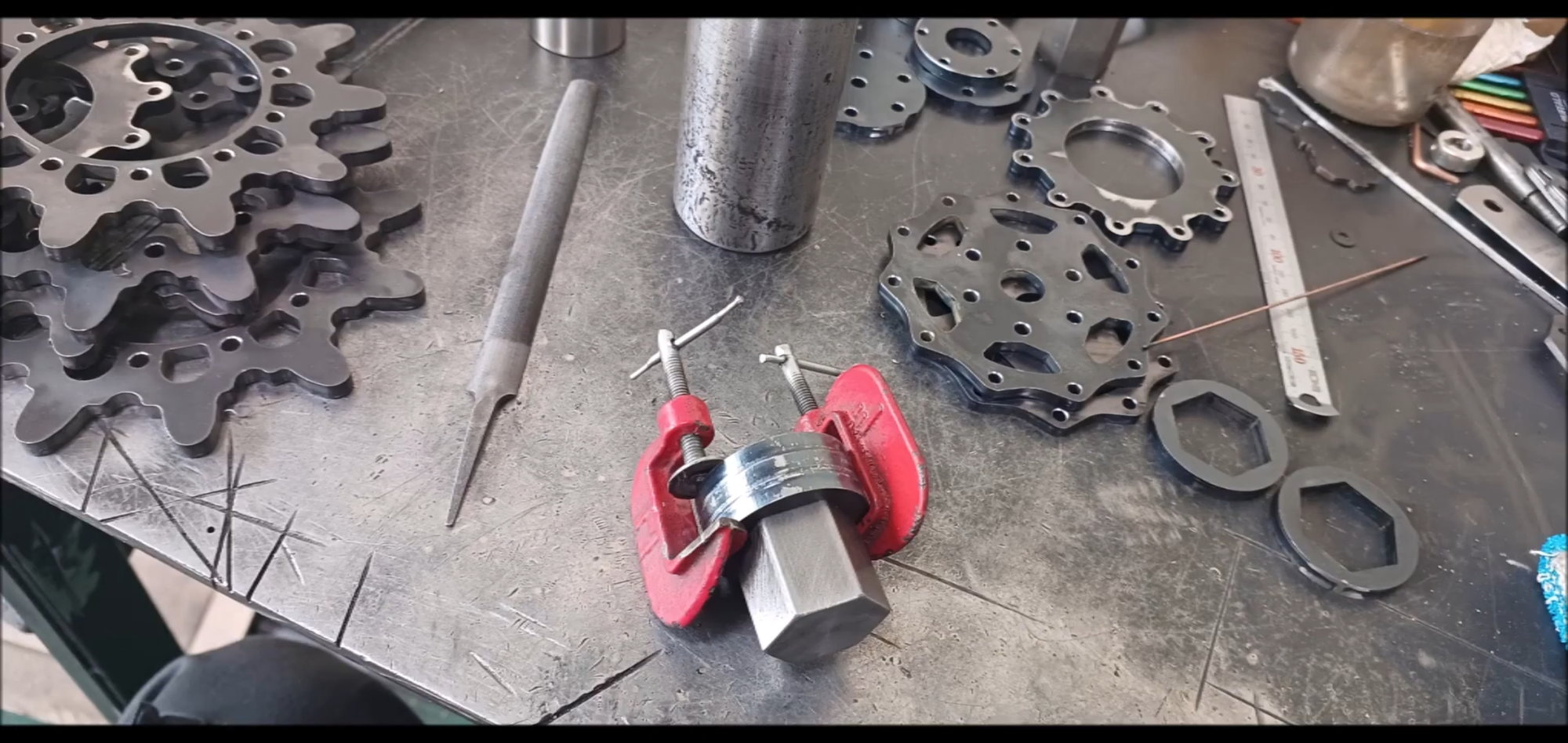
The drive shaft is a hexagonal round bar. The inside of the drive wheel and the hexagonal round bar must be connected very precisely. Therefore, the work is carried out by checking the coupler elaborately.
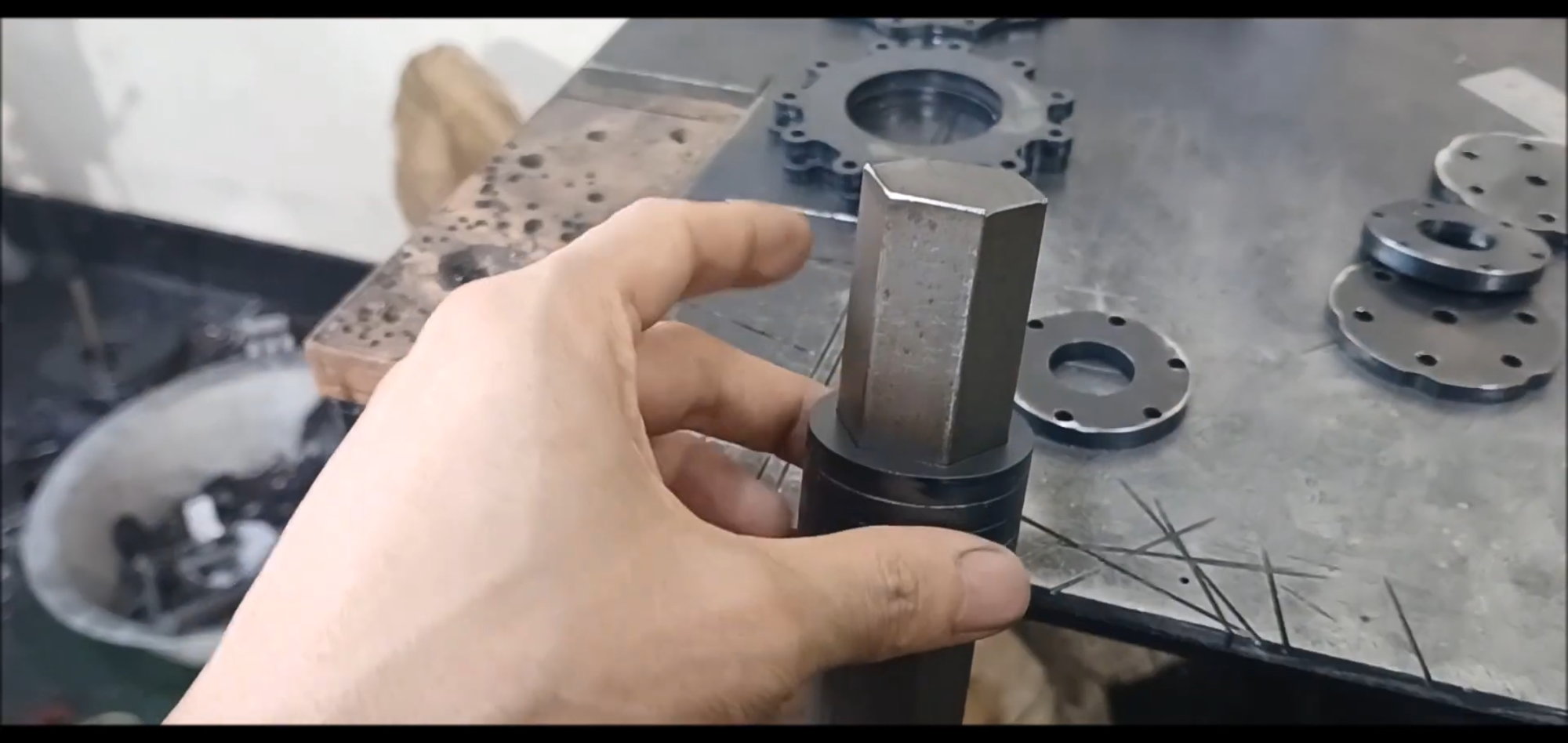
Check the clearance of the hexagonal round bar and coupler.
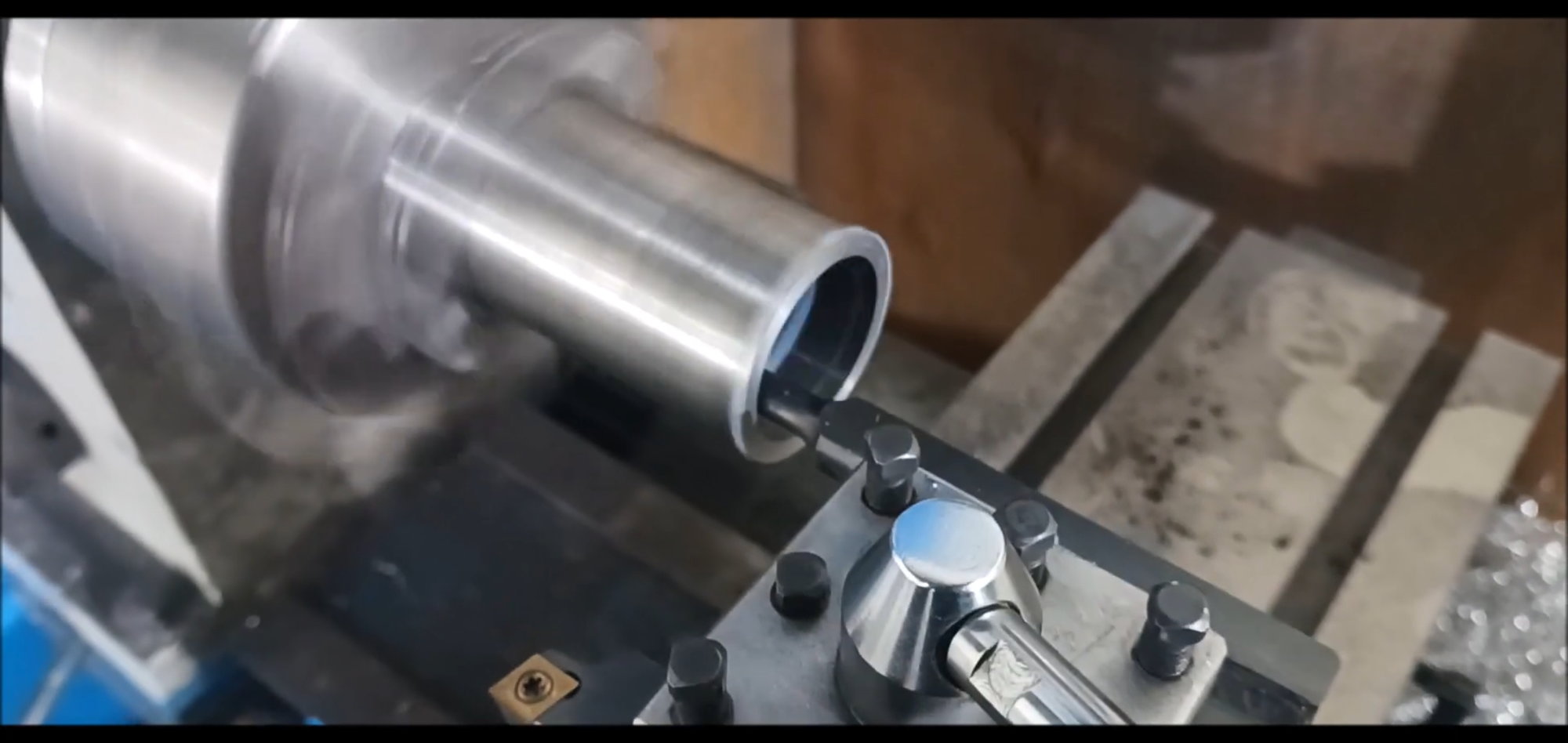
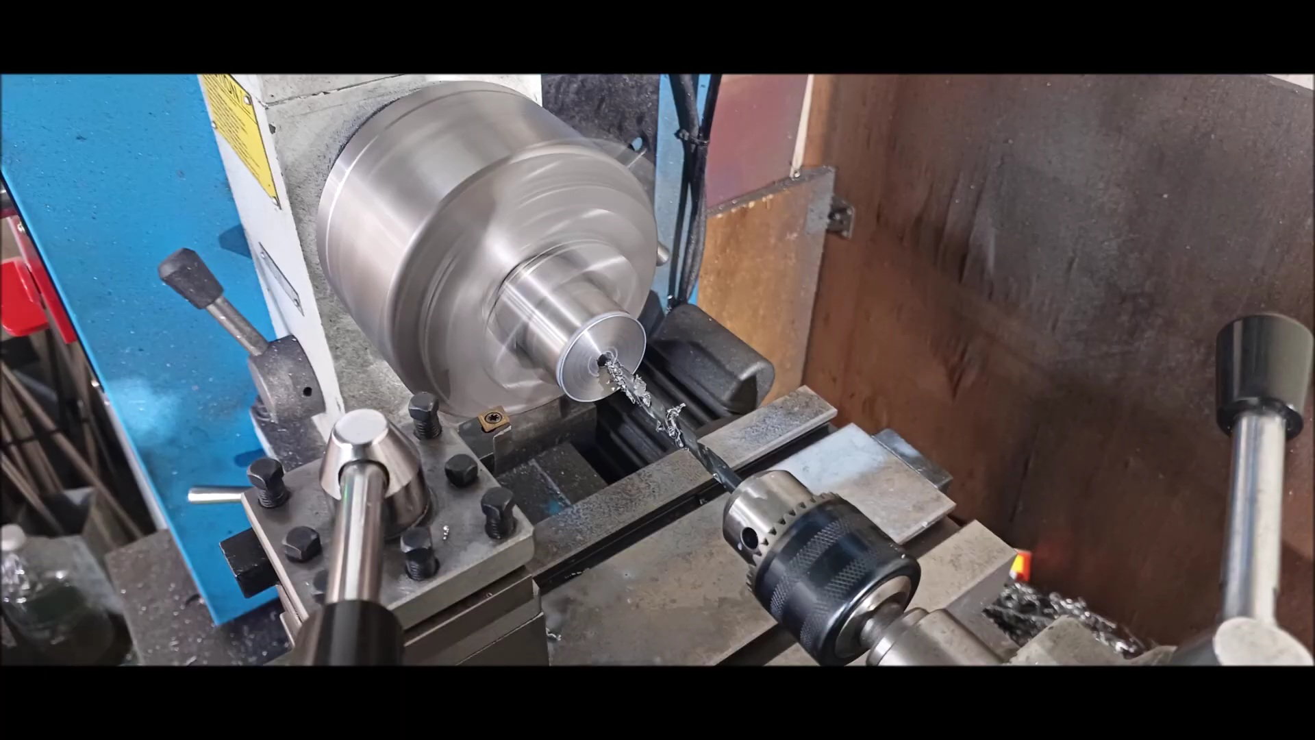
Finely dig out the inner diameter of the pipe to which the coupler outer diameter is to be seated with a shelf machine.
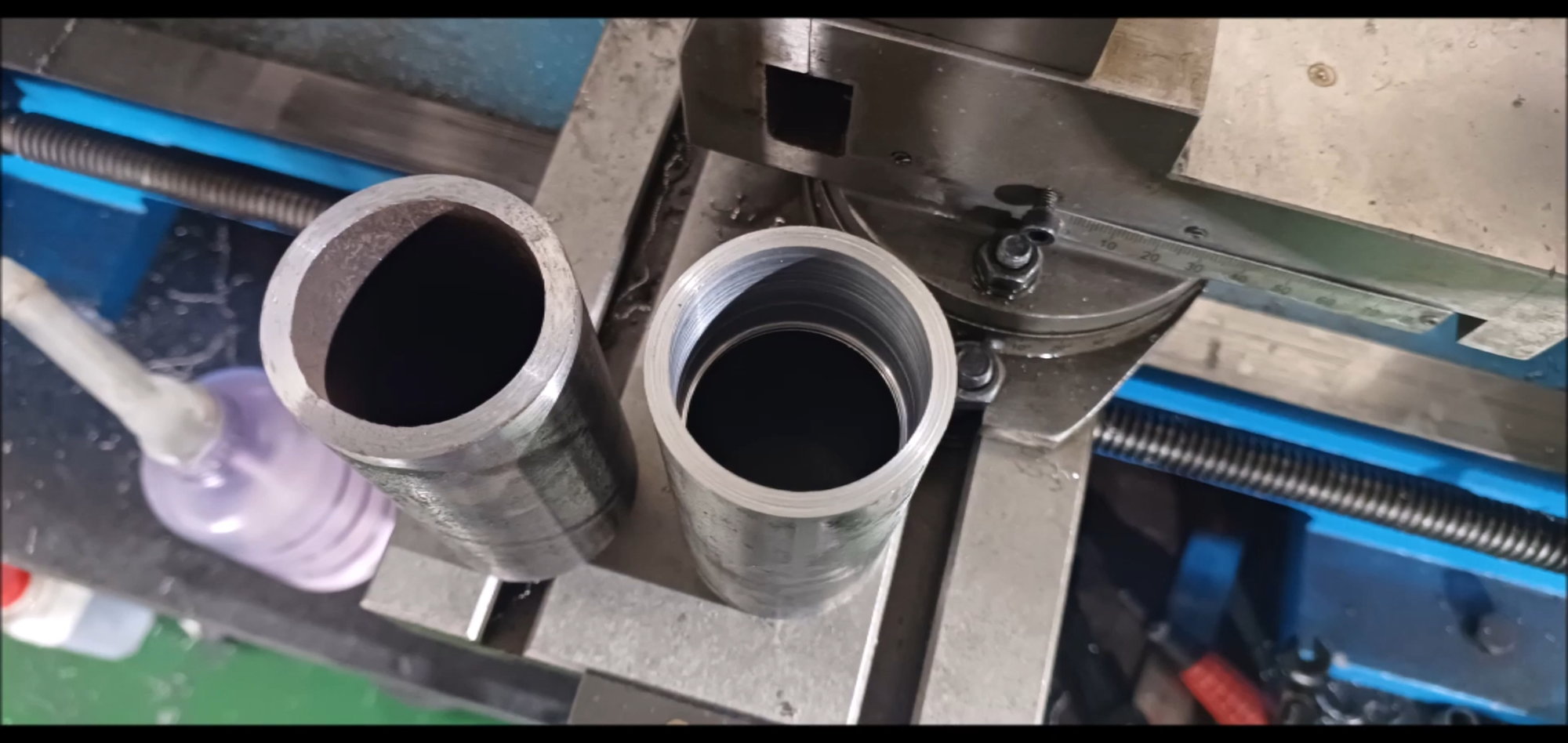
After machining cylindrical pipes dug to fit the coupler diameter at the depth of the design
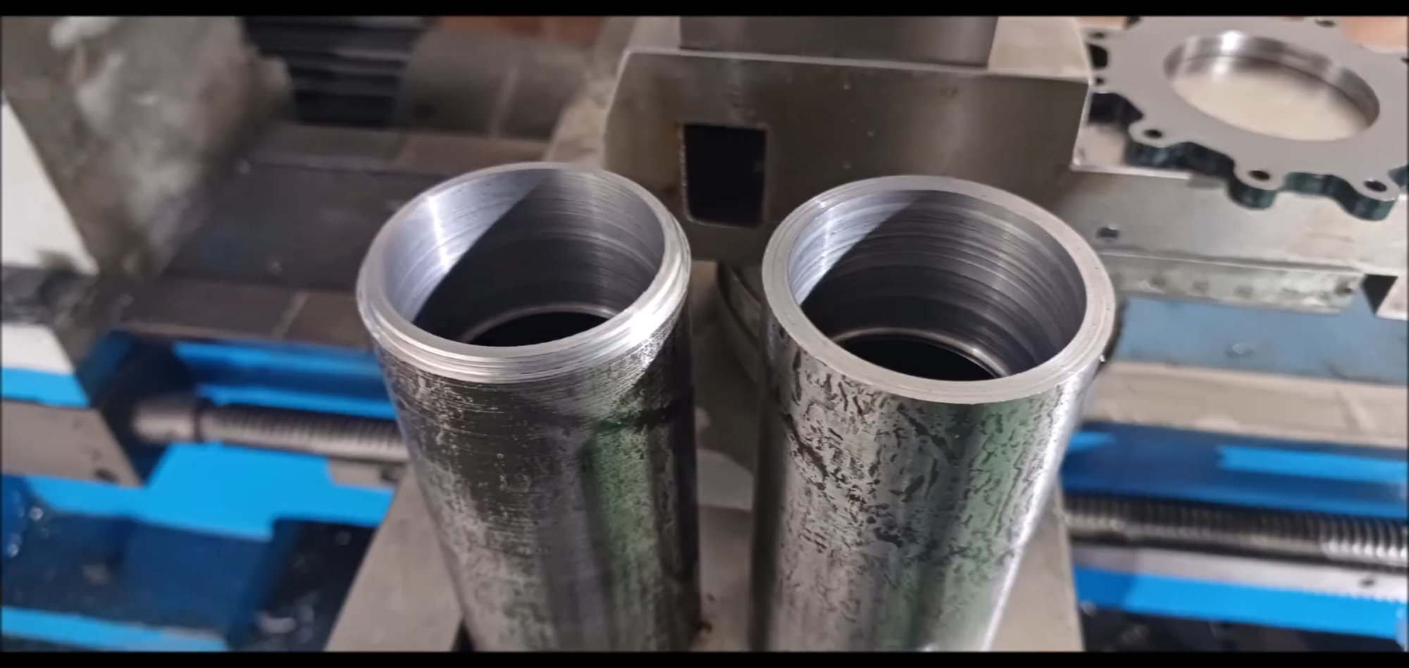
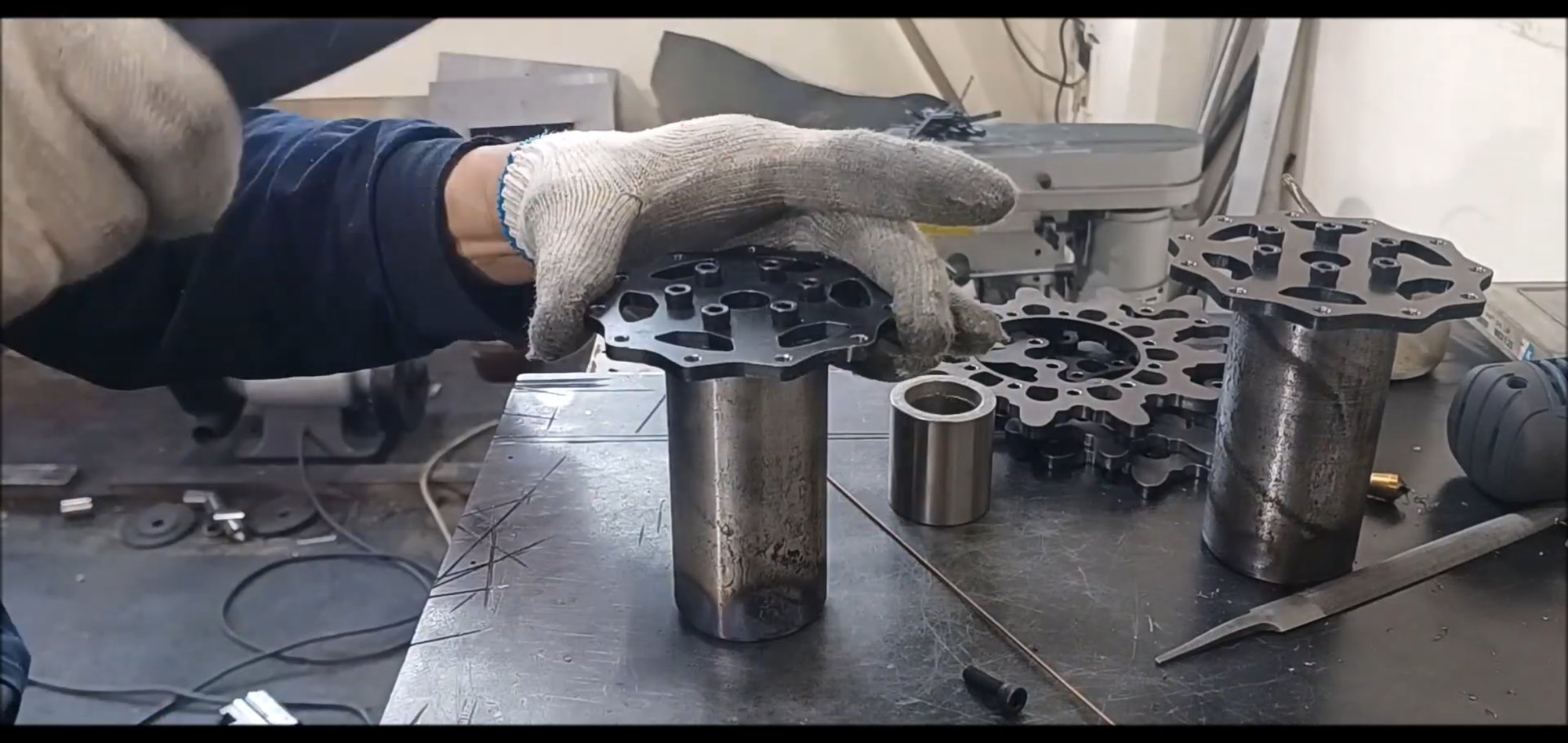
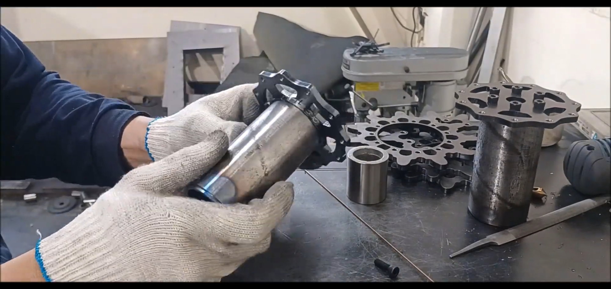
The cylindrical pipe inlet outer diameter is also machined to fit the inner diameter of the sprocket wheel
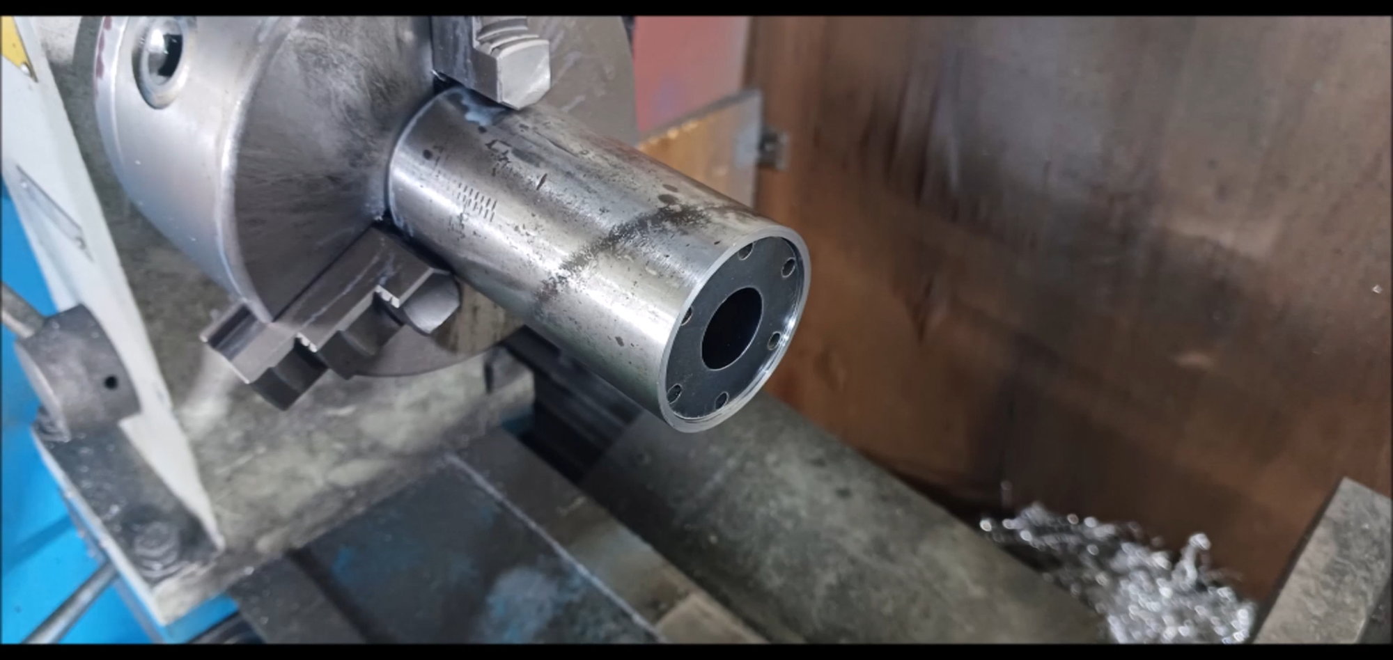
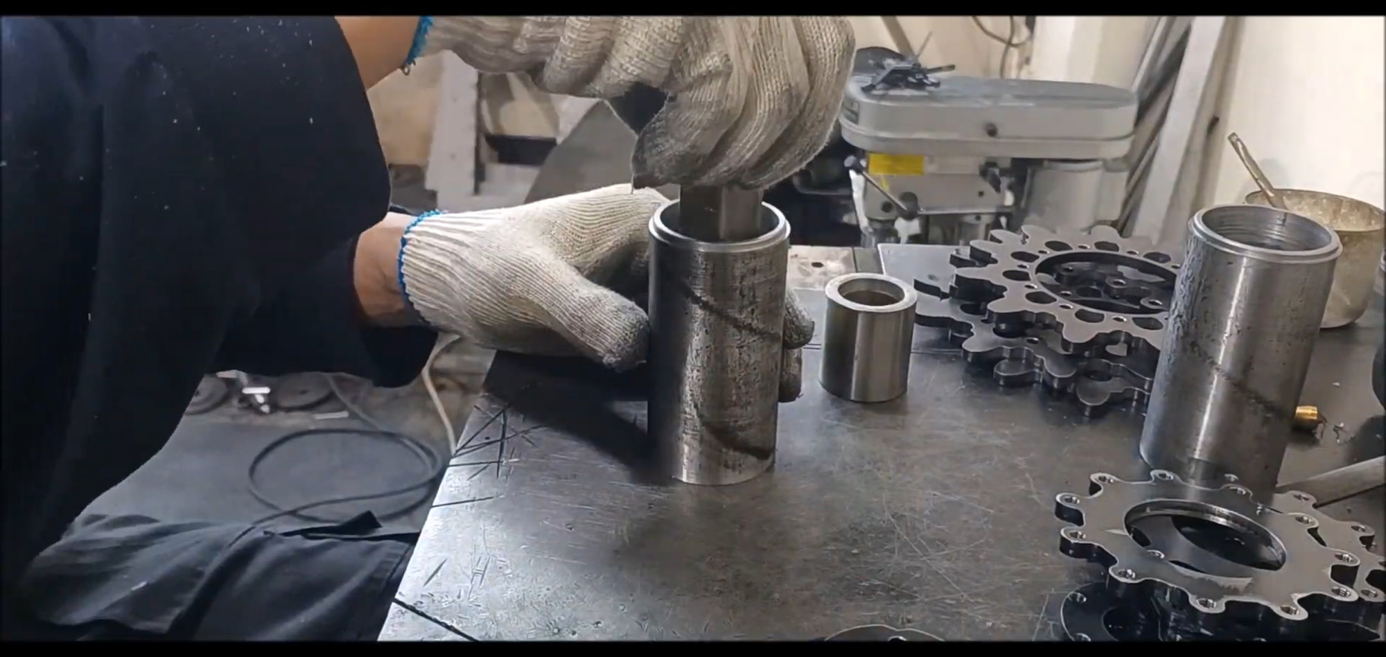
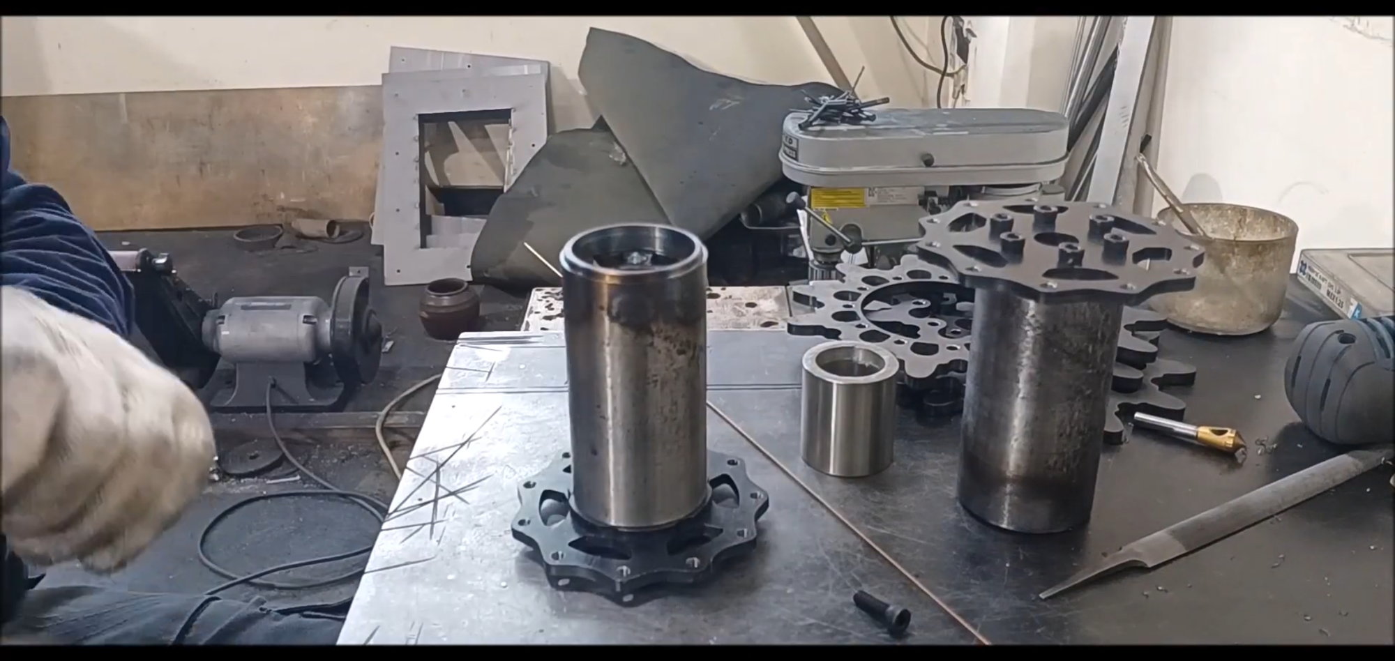
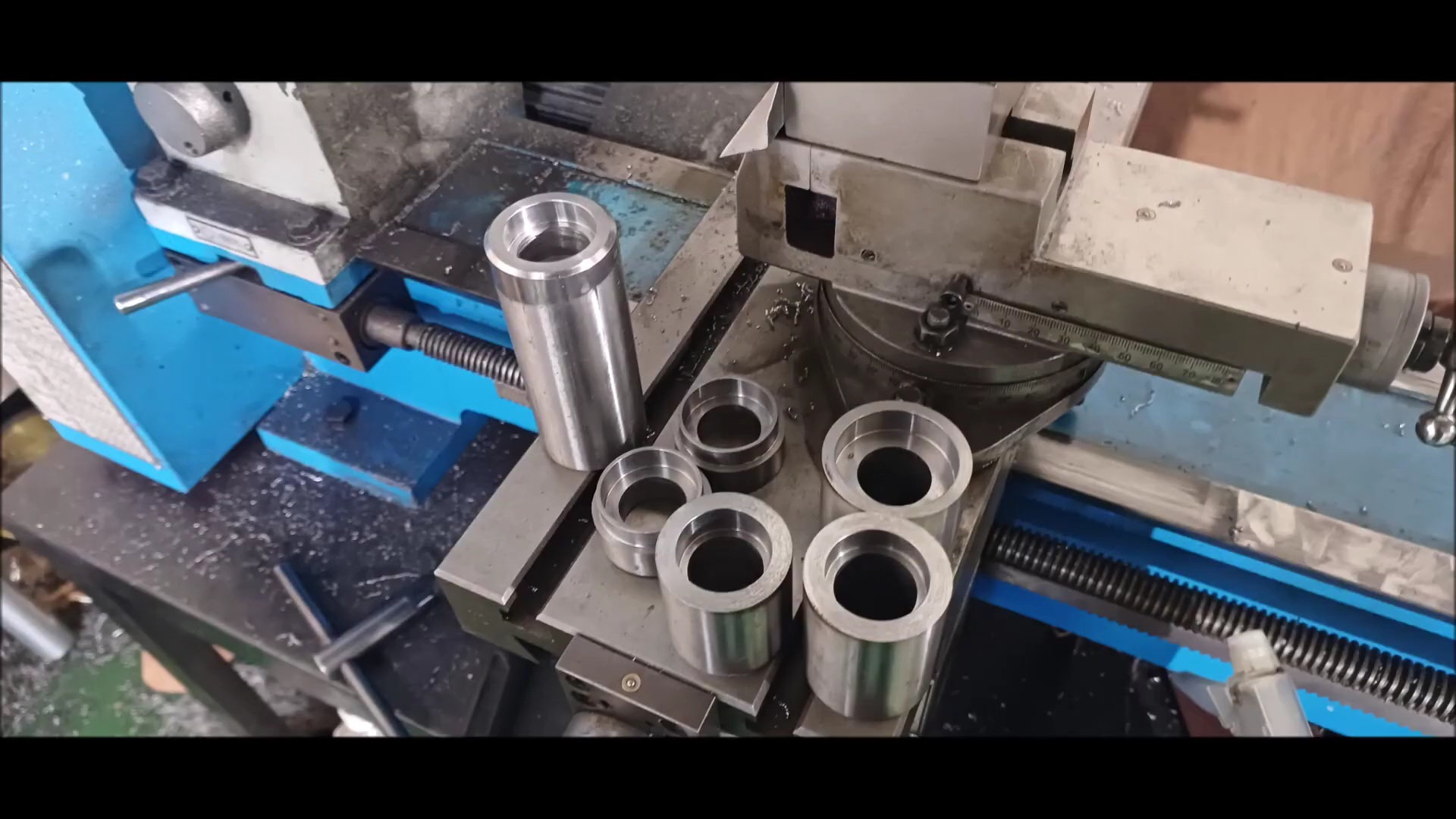
A disk for fixing the sprocket is installed in the pipe opposite to the coupler insertion part
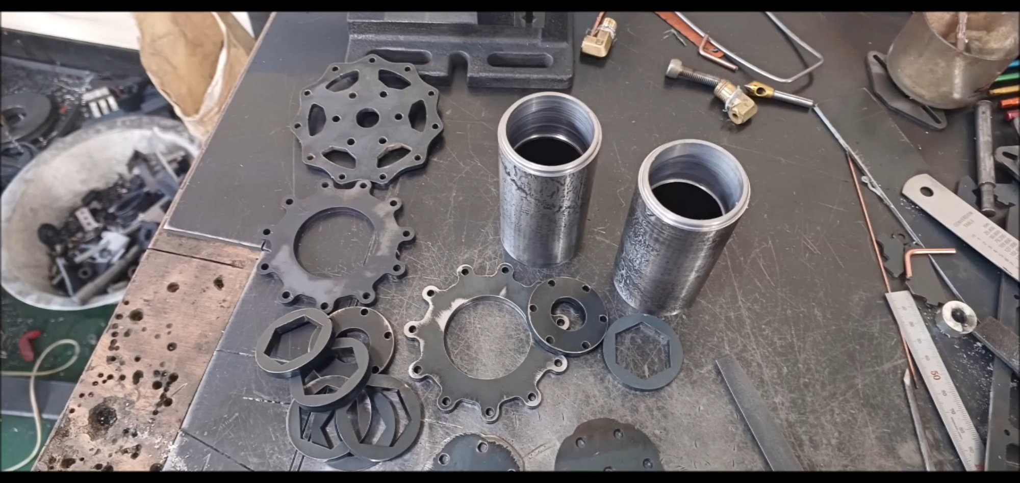
Cylindrical pipe with both ends machined so that both disk and coupler can be inserted
Tap the sprocket connection plate
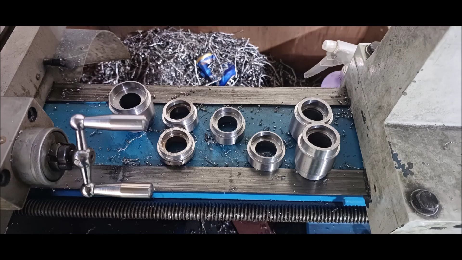
The disk also works as a tap
Sprocket connection disks also tap
Tap operation is limited to all drive wheel components without omission
Thread work is done on all drive wheel components without omission
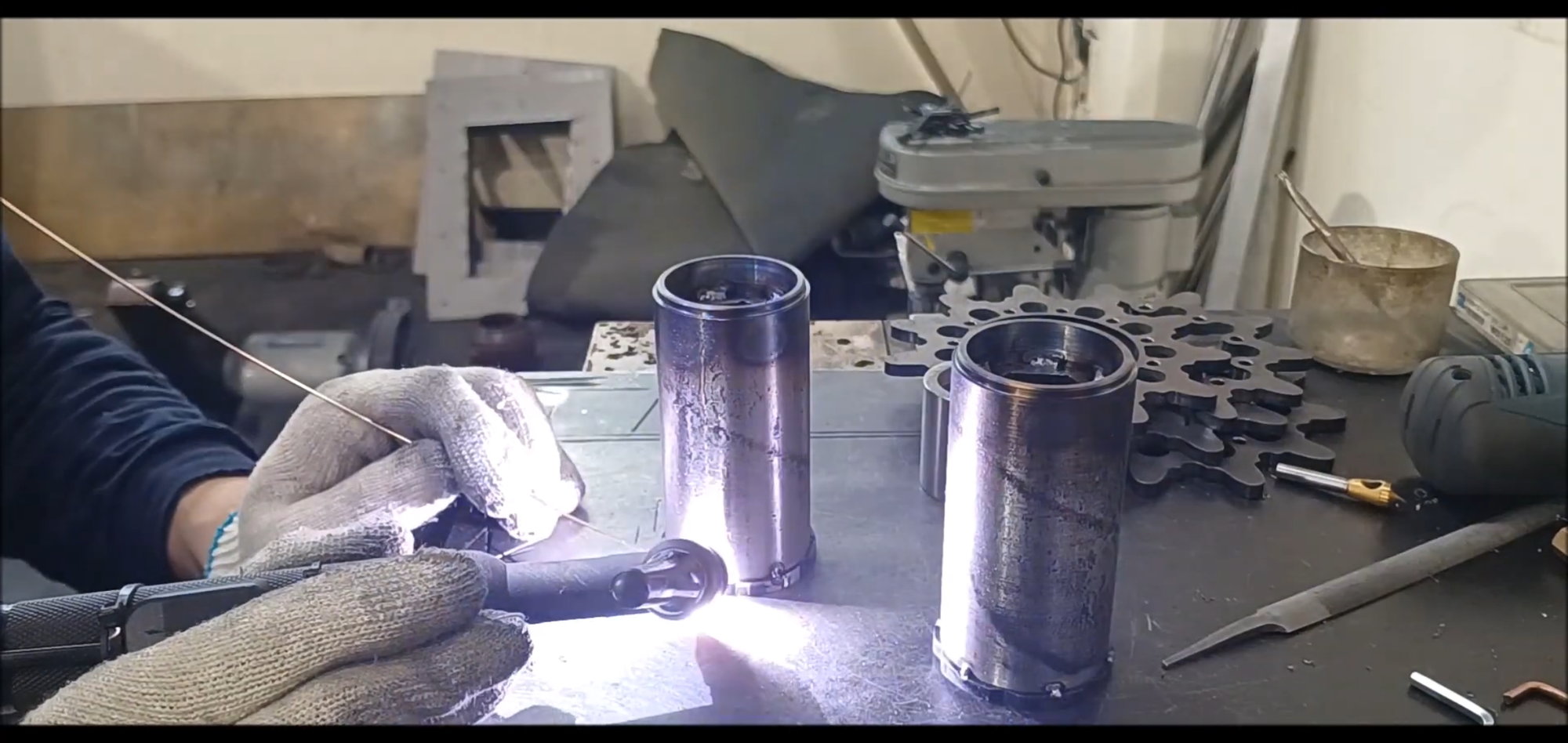
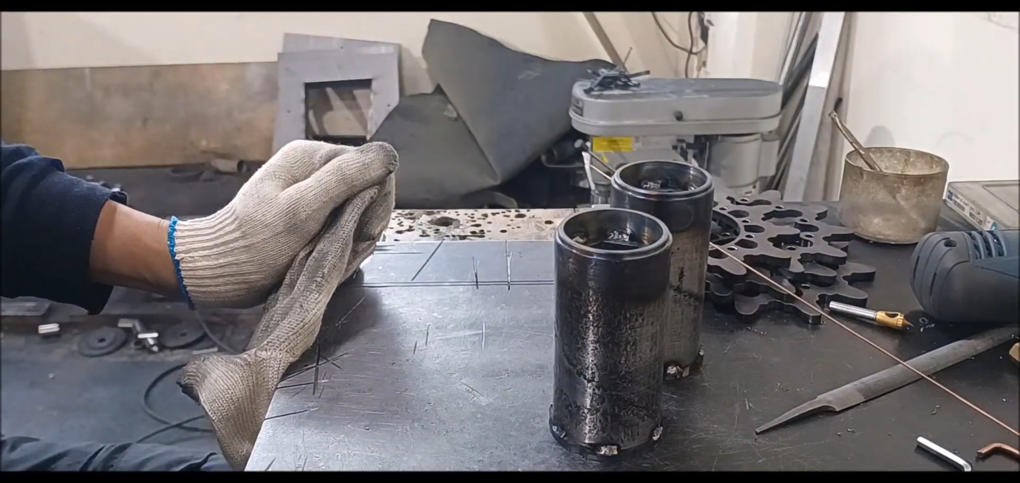
The couplers connected to the hexagonal round bar are welded in three pairs.
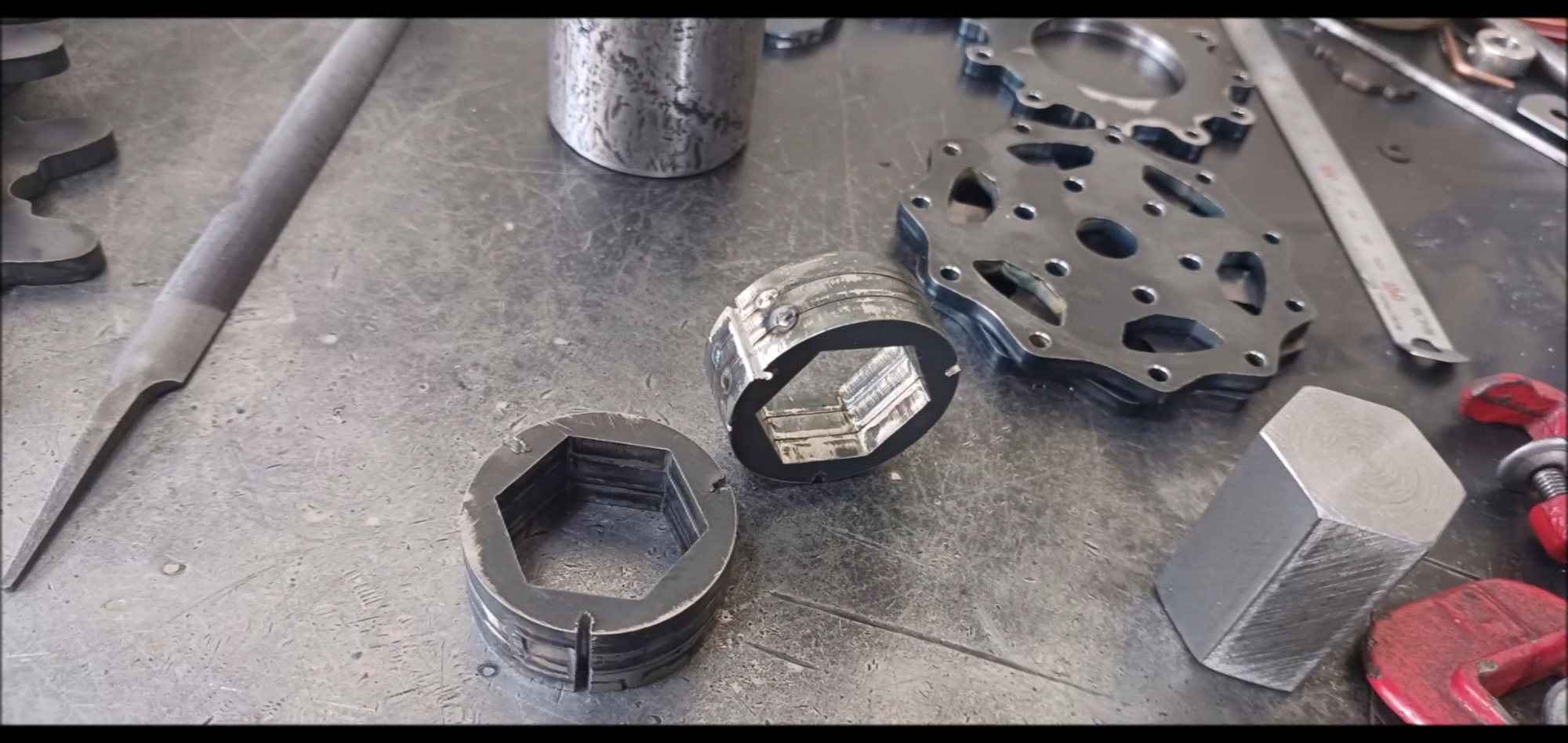
Coupler welded with grooves in a straight line
The coupler is welded thickly
Align the coupler and cylinder vertically with each other for welding
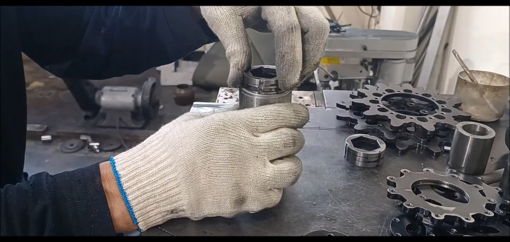
Tap Prevents thermal deformation by inserting a piece of hexagonal round bar into the coupler before welding the coupler and the cylinderand align with a small cylindrical pipe
Prevents thermal deformation by inserting a piece of hexagonal ring rod into the coupler before welding the coupler and cylinder
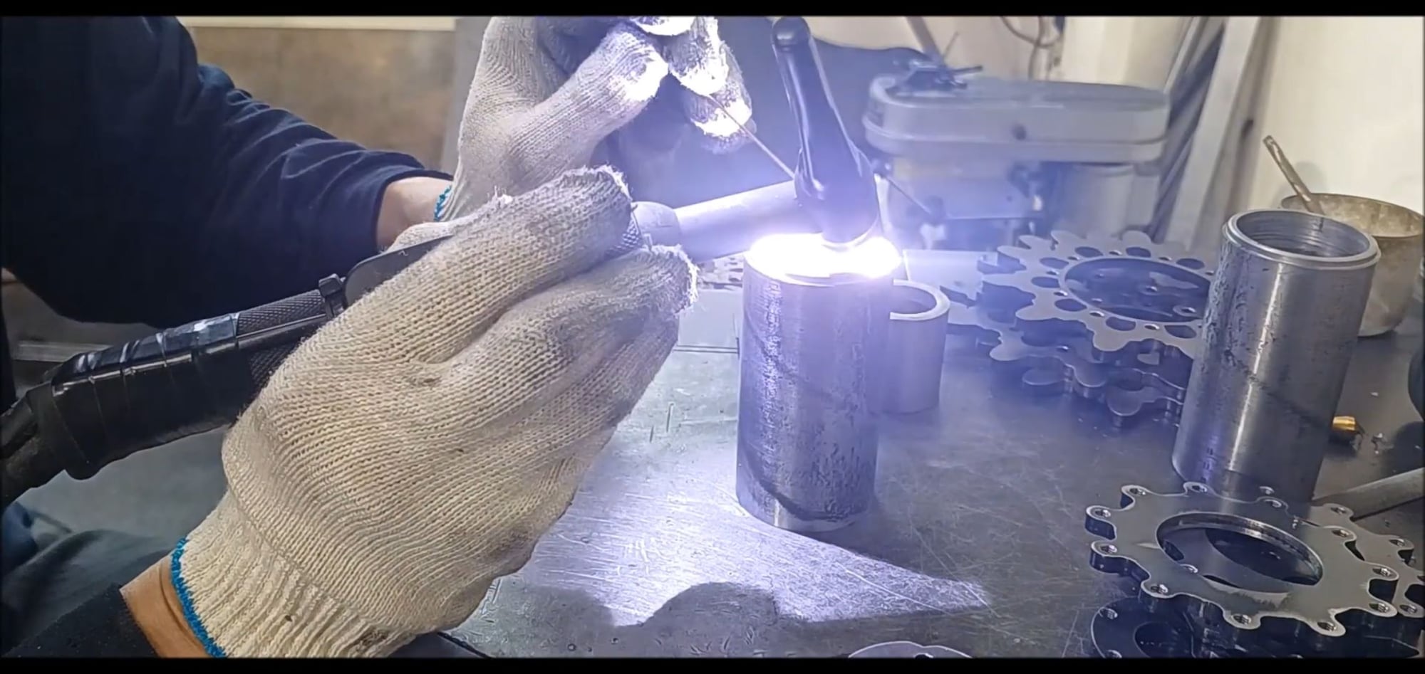
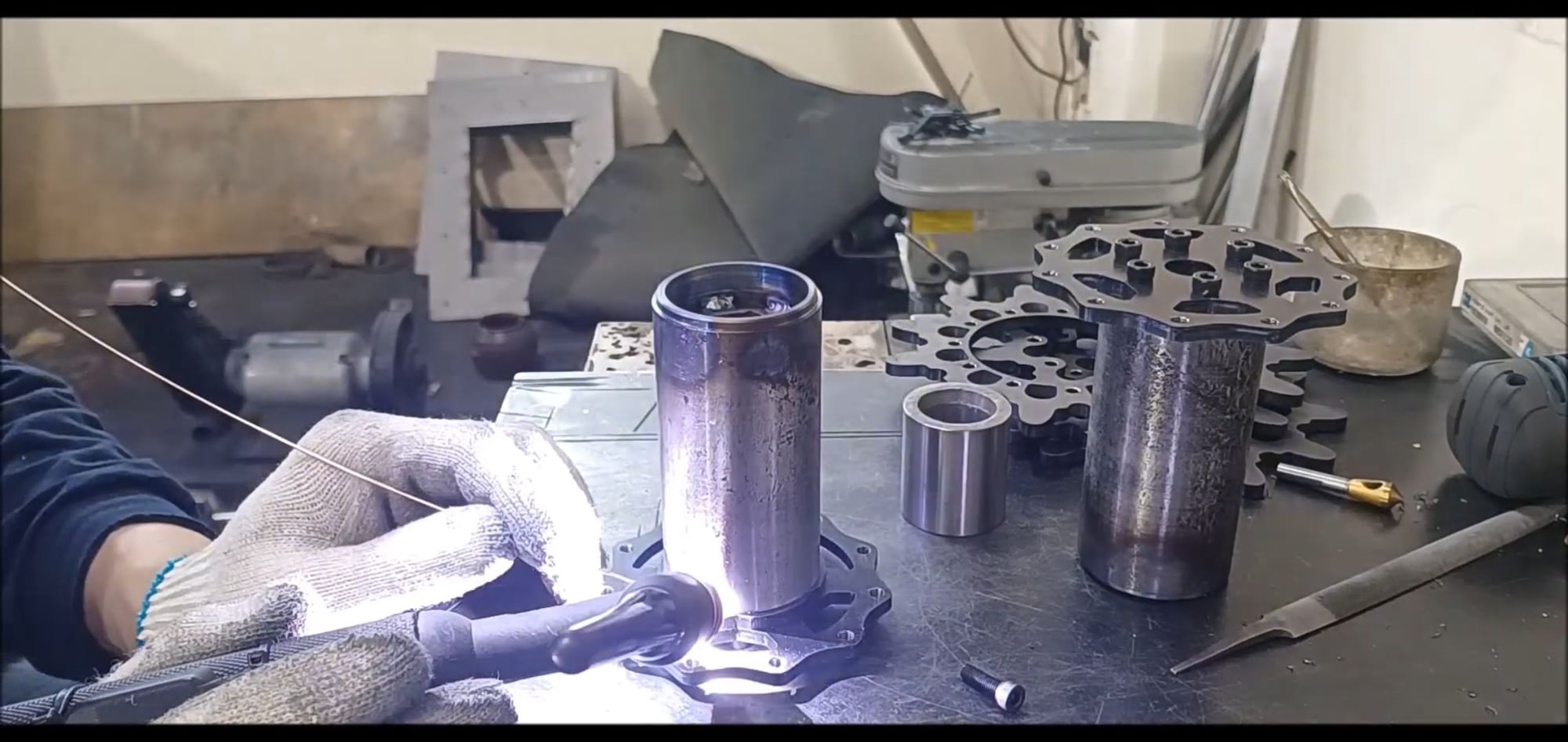
Tig weld the coupling between the coupler and the seal leader
Again, use a small thread reader to heat-deform and hold the deflection
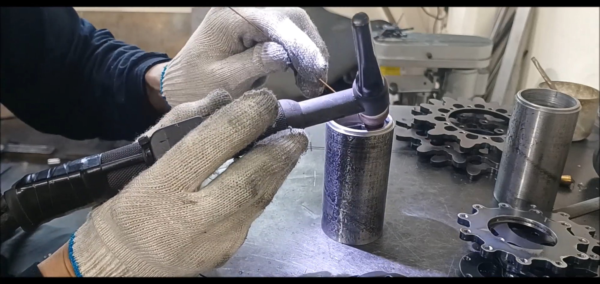
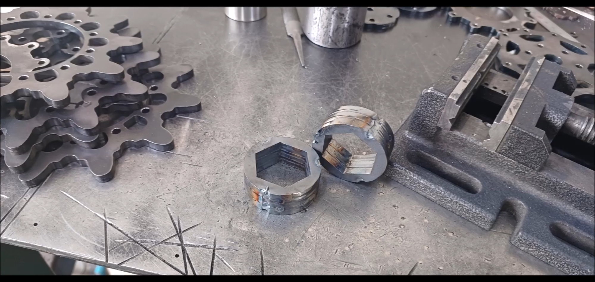
Welded with care for thermal deformation
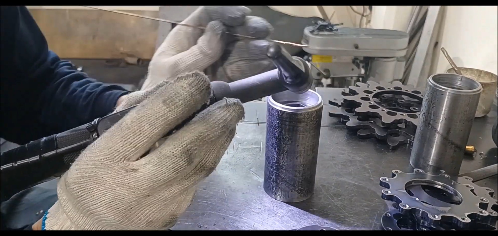
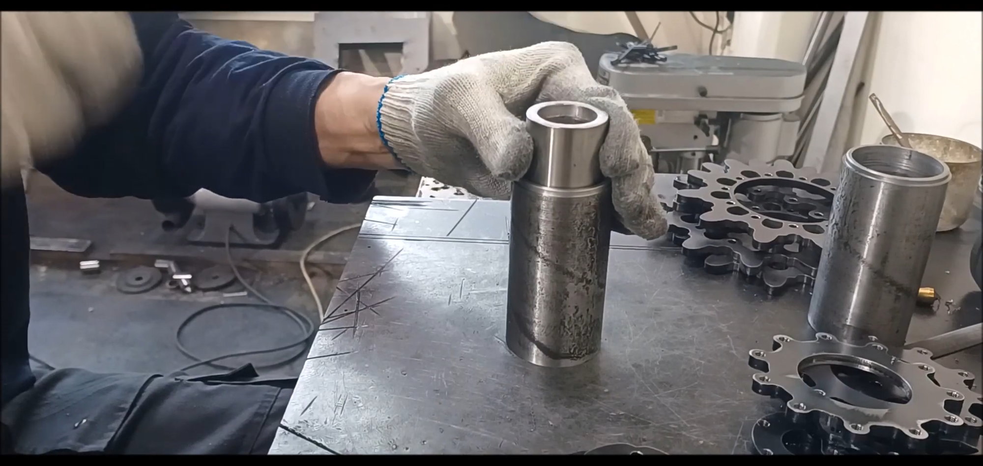
It's a 360 degree welding
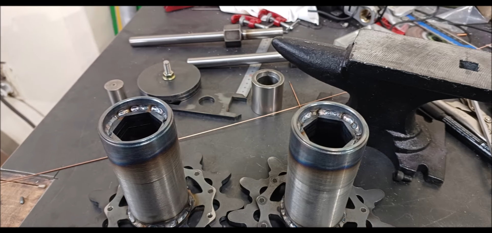
Carefully weld the coupler and cylinder firmly.
Later, the drive shaft to which the hexagonal round bar is coupled is joined in the above shape
will detail the drive wheel operation.
Next time, continuously
Regards,
Young
This is because another project is currently underway first and it needs to be finished.
Today's episode
The material required for drive wheel fabrication is mod steel. Prepare two seamless pipes for laser cutting and drive wheel shafts.
The drive shaft is a hexagonal round bar. The inside of the drive wheel and the hexagonal round bar must be connected very precisely. Therefore, the work is carried out by checking the coupler elaborately.
Check the clearance of the hexagonal round bar and coupler.
Finely dig out the inner diameter of the pipe to which the coupler outer diameter is to be seated with a shelf machine.
After machining cylindrical pipes dug to fit the coupler diameter at the depth of the design
The cylindrical pipe inlet outer diameter is also machined to fit the inner diameter of the sprocket wheel
A disk for fixing the sprocket is installed in the pipe opposite to the coupler insertion part
Cylindrical pipe with both ends machined so that both disk and coupler can be inserted
Tap the sprocket connection plate
The disk also works as a tap
Sprocket connection disks also tap
Tap operation is limited to all drive wheel components without omission
Thread work is done on all drive wheel components without omission
The couplers connected to the hexagonal round bar are welded in three pairs.
Coupler welded with grooves in a straight line
The coupler is welded thickly
Align the coupler and cylinder vertically with each other for welding
Tap Prevents thermal deformation by inserting a piece of hexagonal round bar into the coupler before welding the coupler and the cylinderand align with a small cylindrical pipe
Prevents thermal deformation by inserting a piece of hexagonal ring rod into the coupler before welding the coupler and cylinder
Tig weld the coupling between the coupler and the seal leader
Again, use a small thread reader to heat-deform and hold the deflection
Welded with care for thermal deformation
It's a 360 degree welding
Carefully weld the coupler and cylinder firmly.
Later, the drive shaft to which the hexagonal round bar is coupled is joined in the above shape
will detail the drive wheel operation.
Next time, continuously
Regards,
Young
04-07-2023, 04:06 PM
#37
Thread Starter
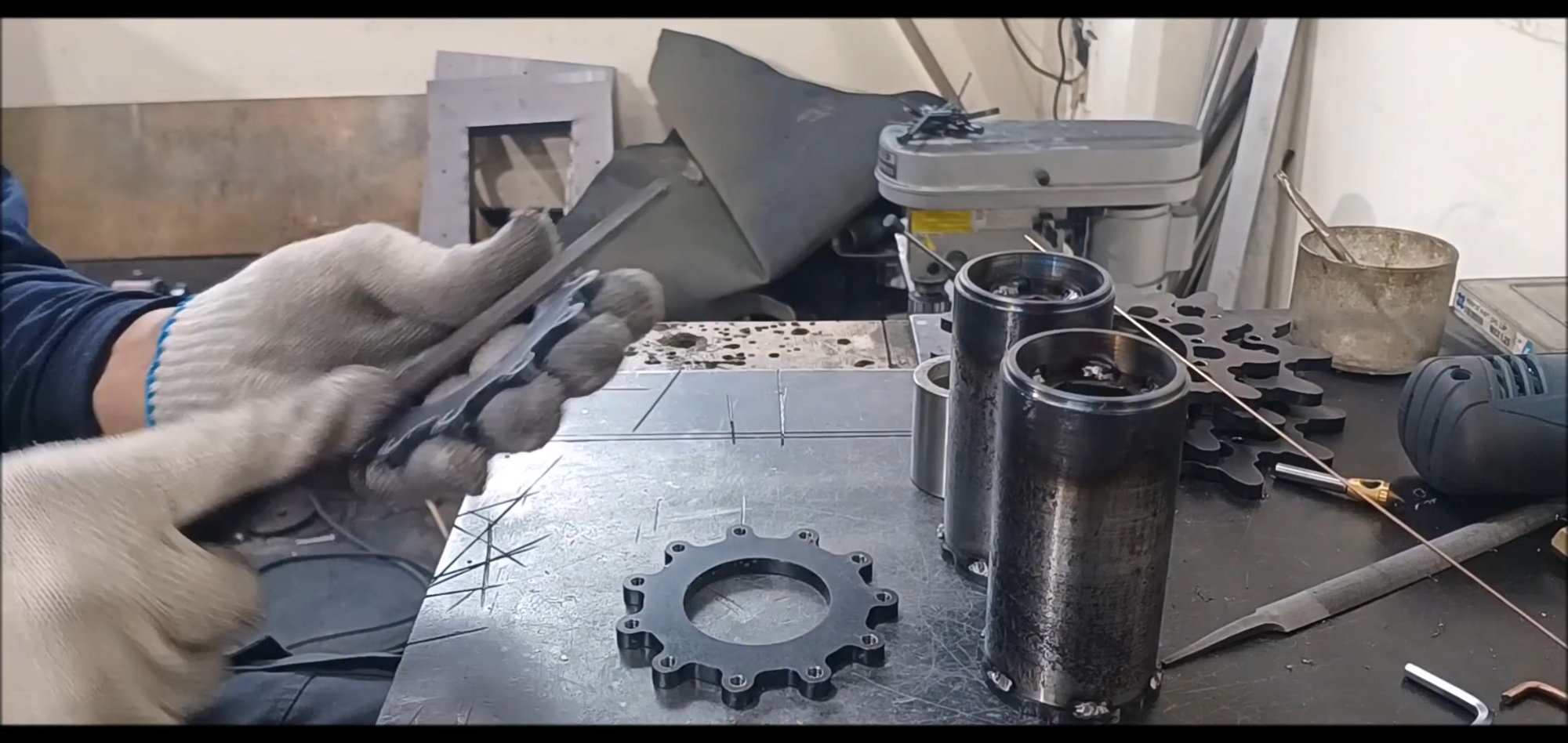
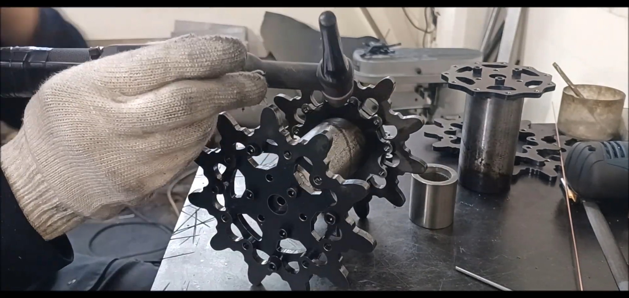
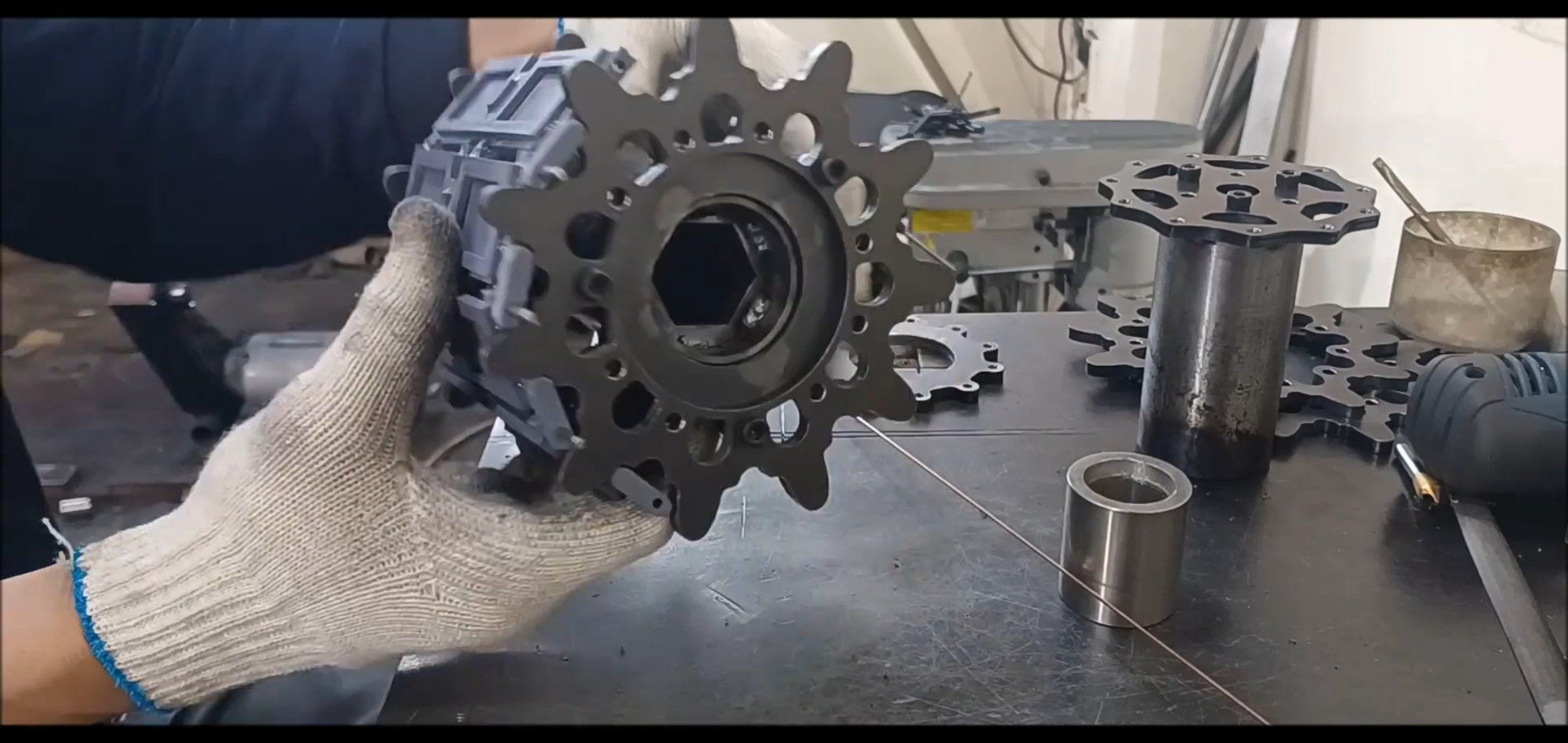
Following the last time, I will introduce the process of making the drive wheels.
The drive wheels are made of steel and will be polished toothed edges smoothly before installing the track.
Starting next week, the production process will be accelerated.
Regards.
Young
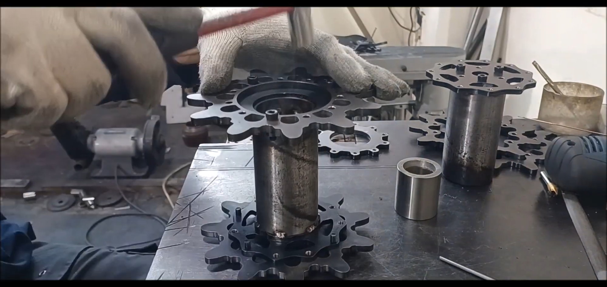
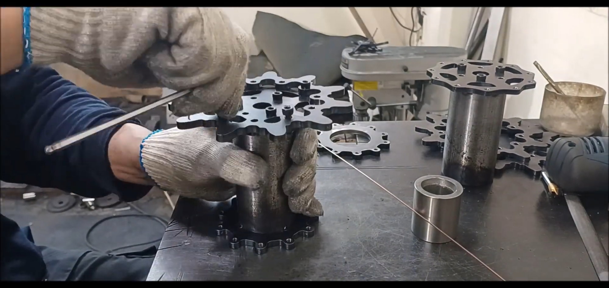
Once the cylindrical structure has been completed, welding will begin to secure the sawtooth gear wheels.
Fix with a temporary fixing wrench bolt.
Complex structures overlap. First, temporarily adjust the guide plate and seal reader insert plate.
Insert the above assembly into the cylinder.
Fine-tune the plane so that it is perpendicular to the cylinder.
Check Status
Welding preparation
Conduct fixed point welding
Remove the guide plate. Wrench bolts did not fall out due to thermal deformation when welding was performed without removal, as in the case of 2022 model
This place will be fixed with a hexagonal bolt later
It's a stressed area, so thorough welding is required
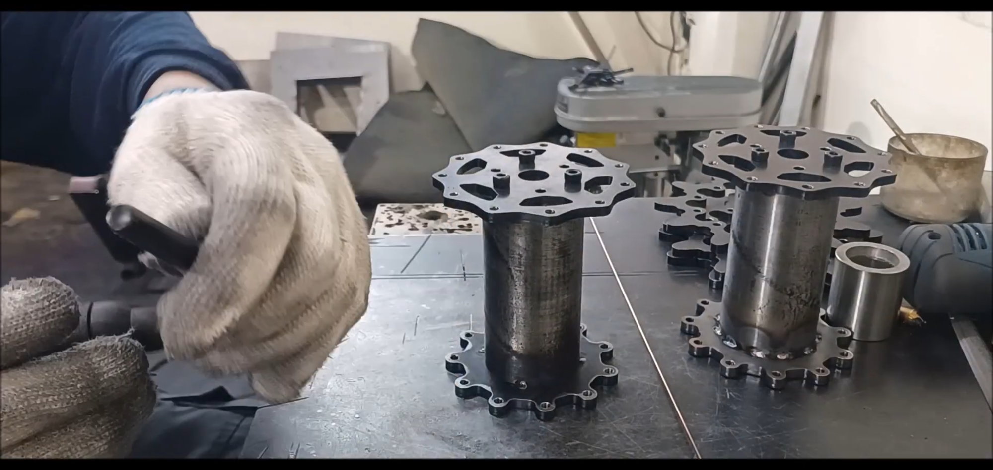
Finished welding fixed parts on top and bottom of cylinder
Welding of the outer fixing plate on the other side of the cylinder

Made in a lifelike shape for structural strength and three-dimensional effect of scale
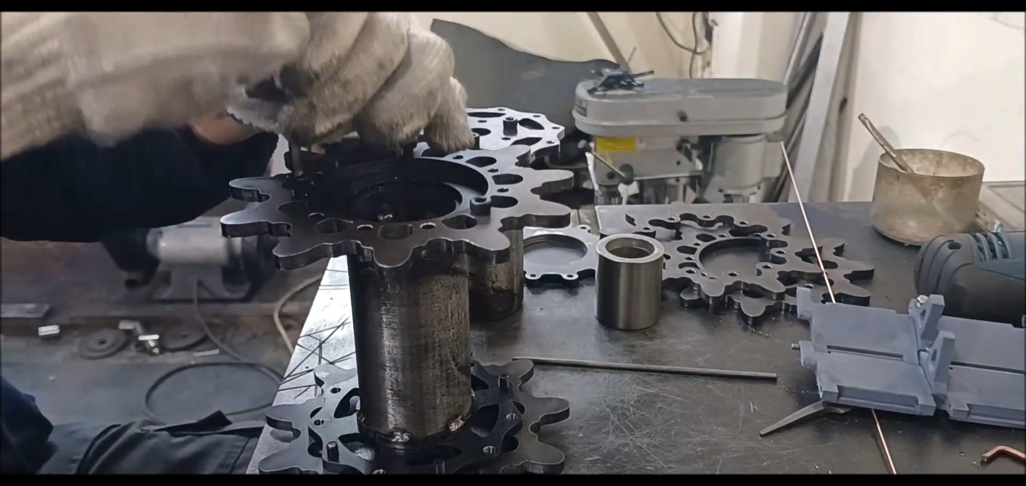
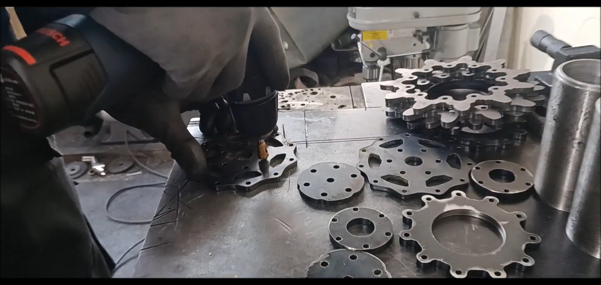
Assemble the top and bottom sawtooth plates and shape them
Position the sawtooth with the 3D sculpture made in episode 1
Position the sawtooth with the 3D sculpture made in episode 1
Temporary fixation with point welds
Modify Location
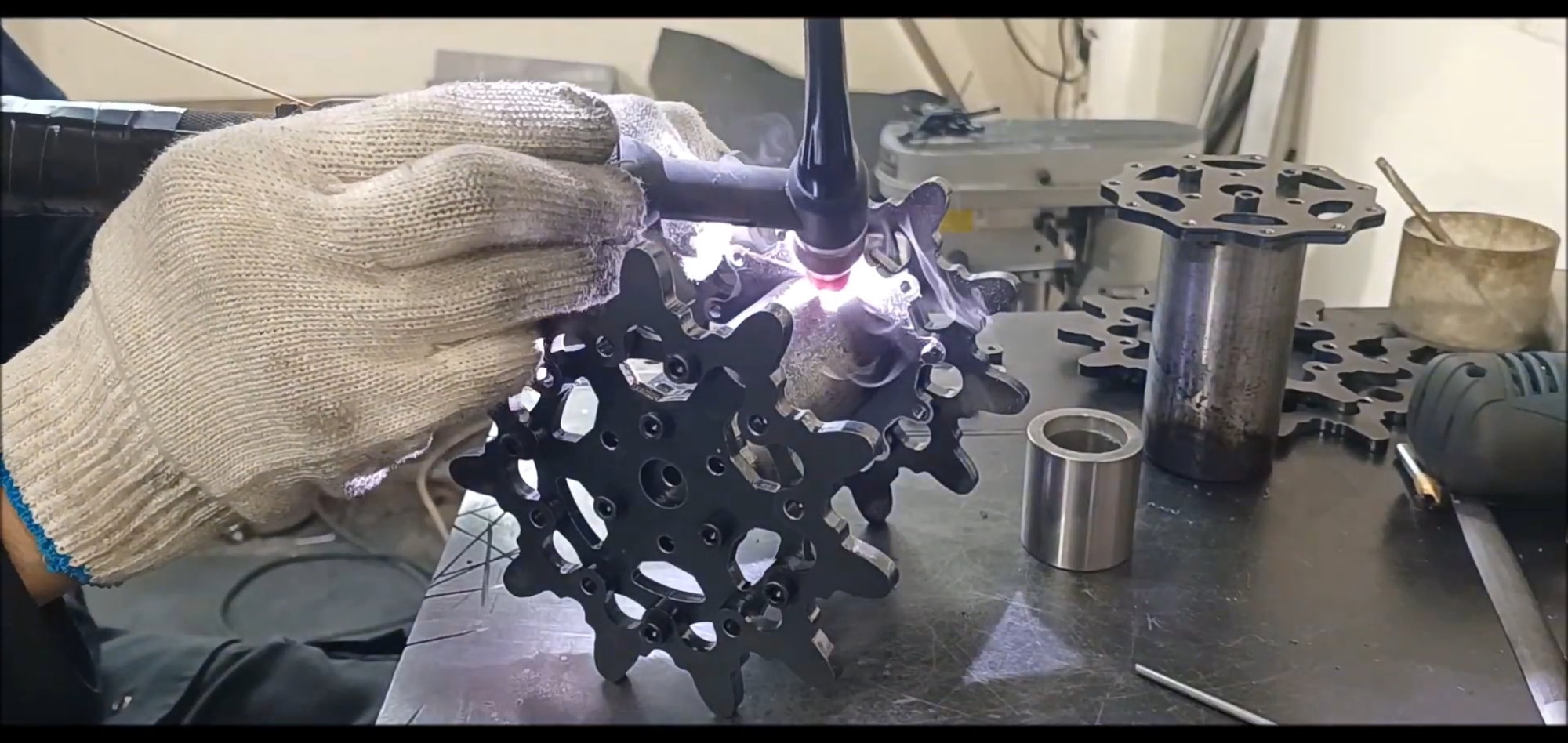
full-scale welding
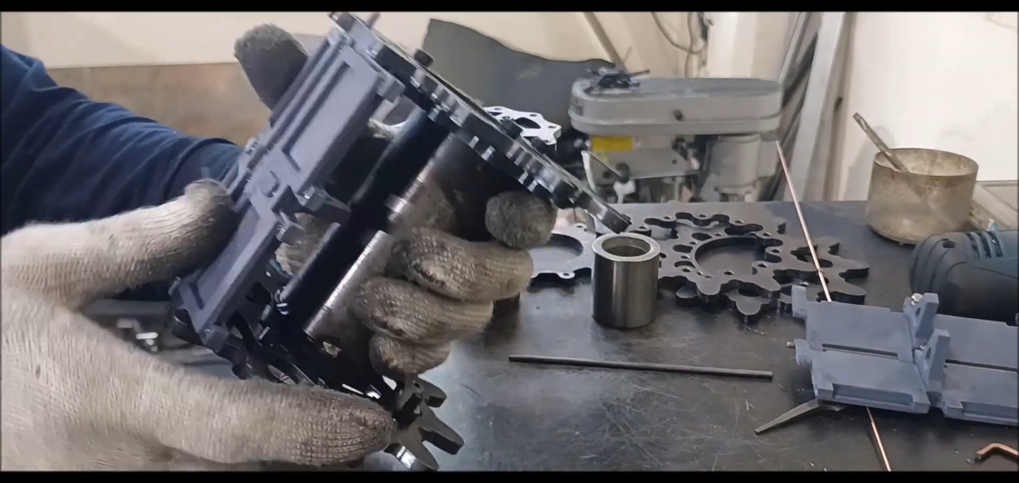
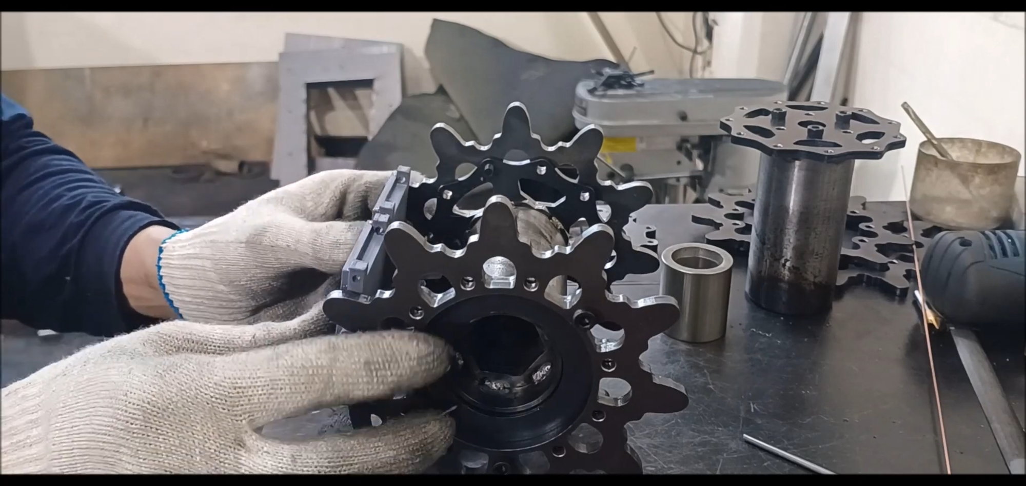
final inspection
final inspection
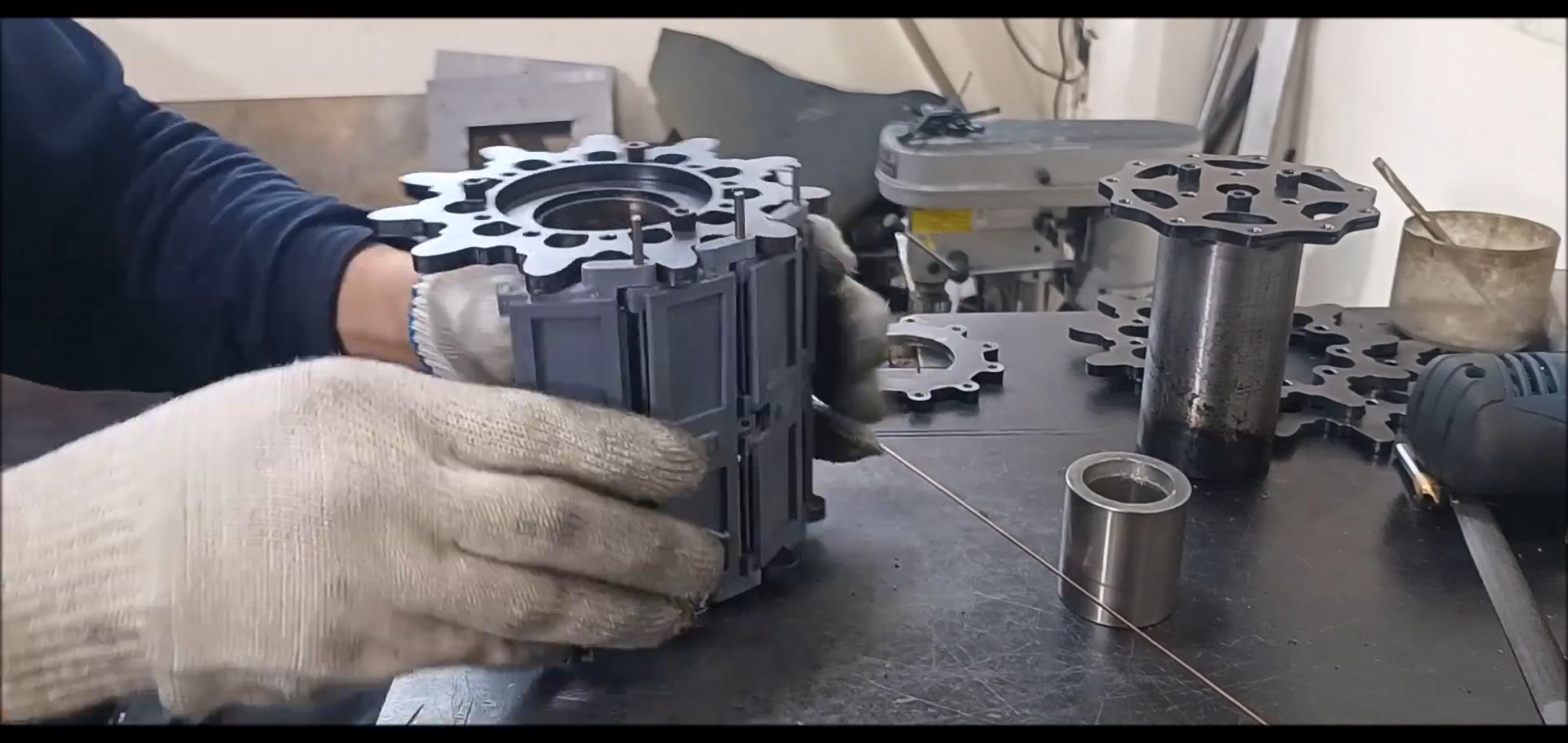
Re-decomposing and waiting
Re-decomposing and waiting
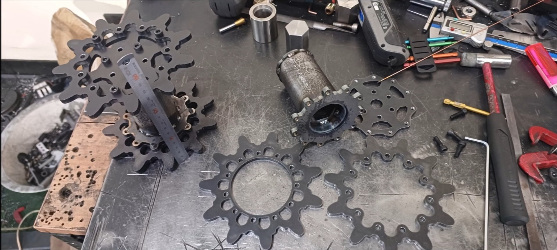
Check and disassemble the sprocket spacing
In the next episode......
The drive wheels are made of steel and will be polished toothed edges smoothly before installing the track.
Starting next week, the production process will be accelerated.
Regards.
Young
Once the cylindrical structure has been completed, welding will begin to secure the sawtooth gear wheels.
Fix with a temporary fixing wrench bolt.
Complex structures overlap. First, temporarily adjust the guide plate and seal reader insert plate.
Insert the above assembly into the cylinder.
Fine-tune the plane so that it is perpendicular to the cylinder.
Check Status
Welding preparation
Conduct fixed point welding
Remove the guide plate. Wrench bolts did not fall out due to thermal deformation when welding was performed without removal, as in the case of 2022 model
This place will be fixed with a hexagonal bolt later
It's a stressed area, so thorough welding is required
Finished welding fixed parts on top and bottom of cylinder
Welding of the outer fixing plate on the other side of the cylinder
Made in a lifelike shape for structural strength and three-dimensional effect of scale
Assemble the top and bottom sawtooth plates and shape them
Position the sawtooth with the 3D sculpture made in episode 1
Position the sawtooth with the 3D sculpture made in episode 1
Temporary fixation with point welds
Modify Location
full-scale welding
final inspection
final inspection
Re-decomposing and waiting
Re-decomposing and waiting
Check and disassemble the sprocket spacing
In the next episode......
The following 4 users liked this post by PE YOUNG:
04-08-2023, 02:13 PM
#38
That process is a joy to watch. Thank you for documenting it.
The following users liked this post:
PE YOUNG (04-08-2023)
04-08-2023, 02:34 PM
#39

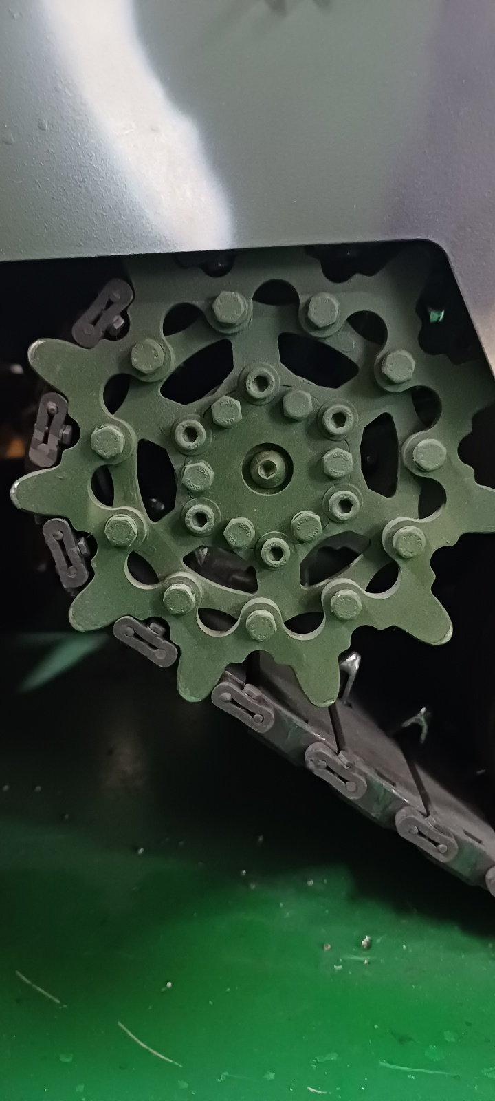
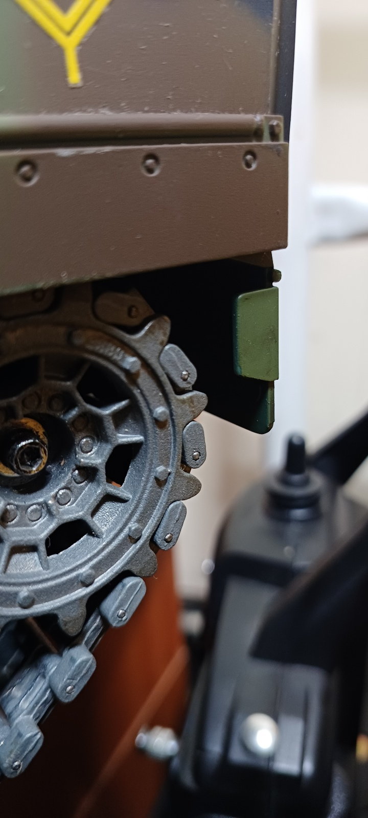
If you compare the two drive sprockets, you'll notice the teeth on the model protruding WAY past the Links of the Tracks which I think might pose an issue for either the Track rolling on or off the Sprockets.
On a somewhat related note... Are they reusing parts of the Leopard 2 Family? That inner Hub of the Drive Sprocket looks kinda familiar 🤔🤨
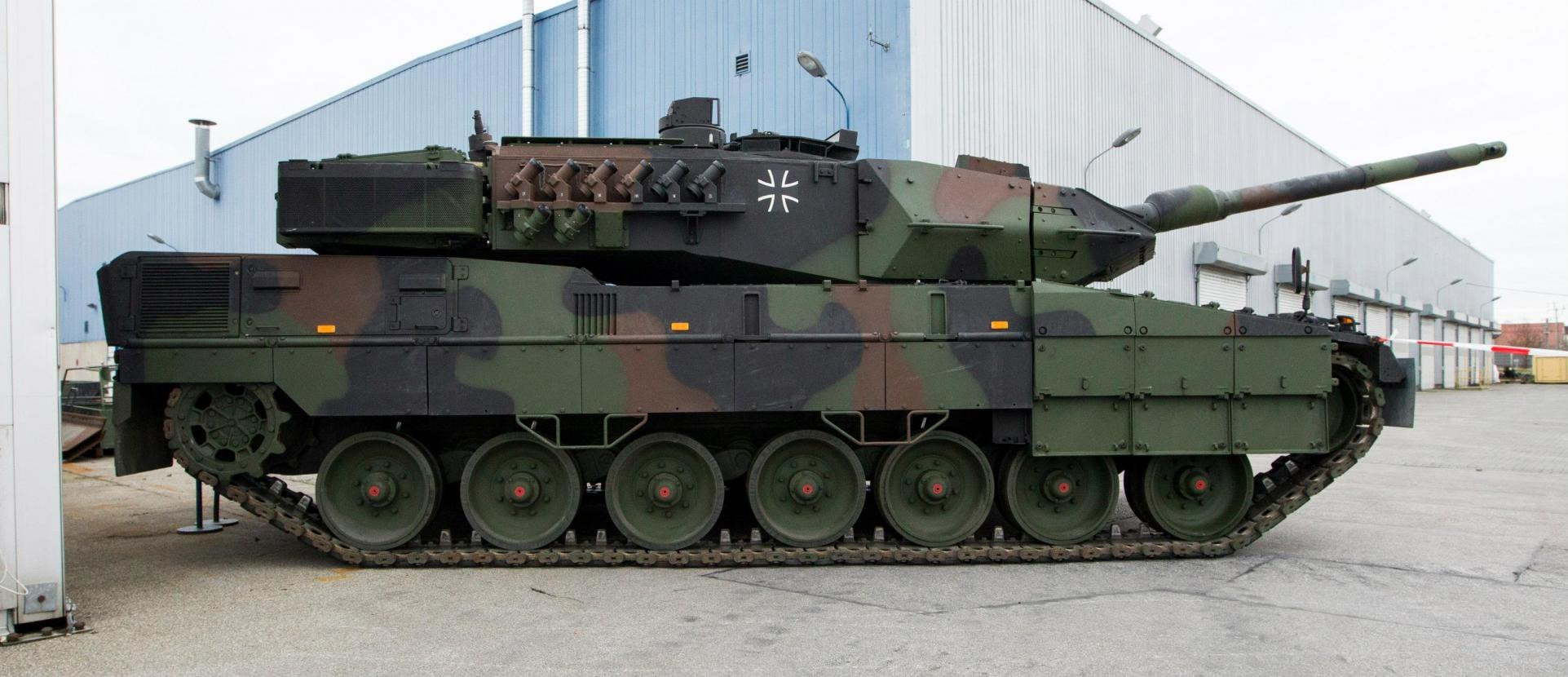
On a somewhat related note... Are they reusing parts of the Leopard 2 Family? That inner Hub of the Drive Sprocket looks kinda familiar 🤔🤨
 04-08-2023, 06:02 PM
#40
Thread Starter
If you compare the two drive sprockets, you'll notice the teeth on the model protruding WAY past the Links of the Tracks which I think might pose an issue for either the Track rolling on or off the Sprockets.
On a somewhat related note... Are they reusing parts of the Leopard 2 Family? That inner Hub of the Drive Sprocket looks kinda familiar 🤔🤨
On a somewhat related note... Are they reusing parts of the Leopard 2 Family? That inner Hub of the Drive Sprocket looks kinda familiar 🤔🤨
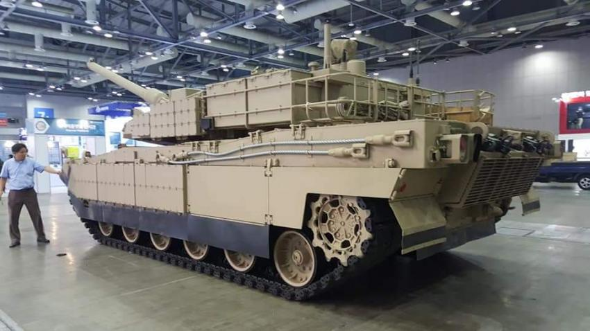
Most Western-made tanks weigh over 60 TON and produce tracks using the German Leopard's trackmaking technology.
In the 1970s, when the U.S. developed a MBT in collaboration with Germany, it conceived a track called the T-158.
The tracks of recent NATO standard Western armoured equipment are similar.
Armoured tracks in Korea will be replaced with rubber tracks in the future.
South Korea has decided to independently localize its rubber orbit under the auspices of the Institute of Defense Development, as it has now used products made by Canada's Soucy Defense for its Redback infantry armoured vehicles.
Please refer to the link below for Korea's track production.
https://www.lstrackshoe.co.kr:8003/products/
In this model fabrication, the track will be somewhat simplified, considering the convenience and durability of fabrication rather than scale precision. (See previous news)
Regards,
Young
Last edited by PE YOUNG; 04-08-2023 at 06:09 PM.
The following users liked this post:
tankme (04-08-2023)
04-15-2023, 10:17 PM
#42
Thread Starter
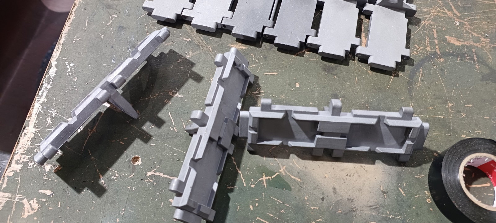
The tank manufacturer decided to manufacture and install the caterpillar of the 2023 1/5 scale Black Panther tank (project name: ic2504) by casting method. The optimal method is to increase production efficiency and reduce the number of iterations.
The shape of the track is somewhat different from the actual one, but it is strong and has increased assembly efficiency.
The production is outsourced processing, and the outsourced production has been requested today.
Regards,
Young
Upper shape of caterpillar
the lower appearance of the caterpillar
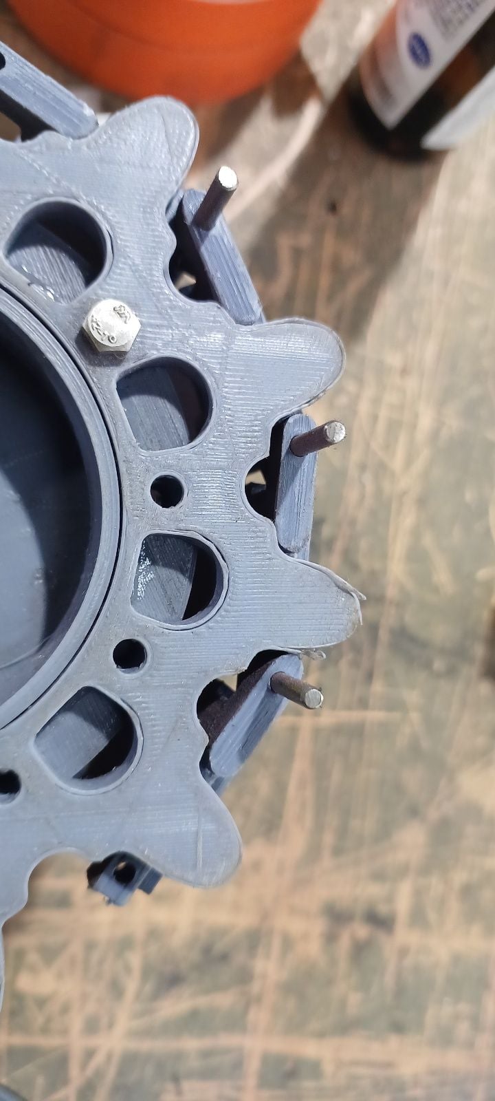
The sample of the casting track by outsourcing arrived the other day.
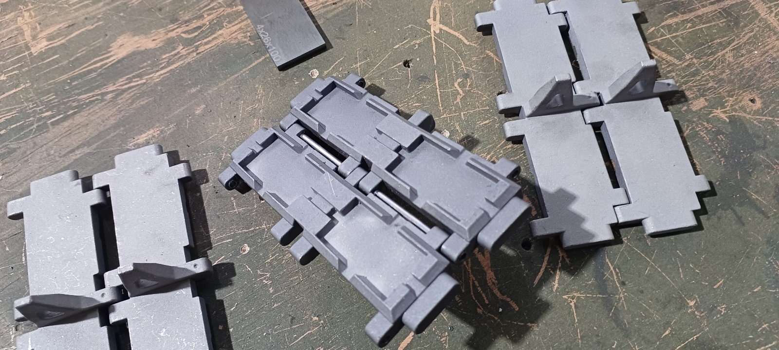
The connection is more natural and powerful
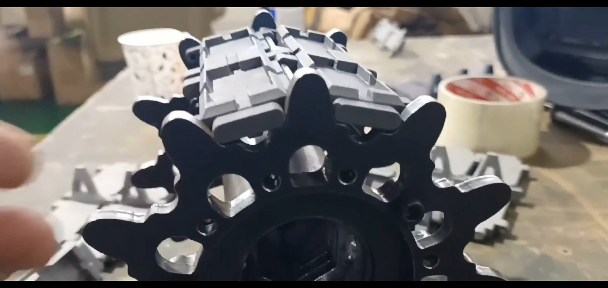
Check by hanging it on the sprocket that was made last time
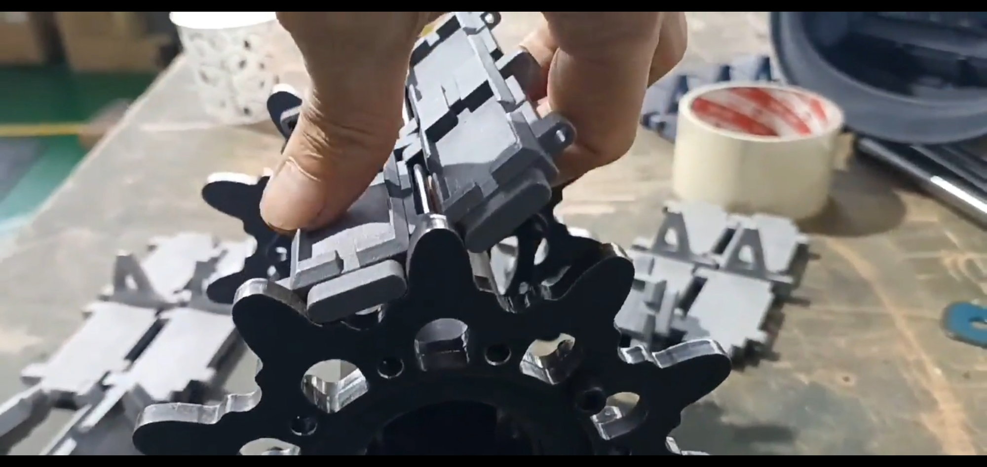
Tightly operated to show less track deviations
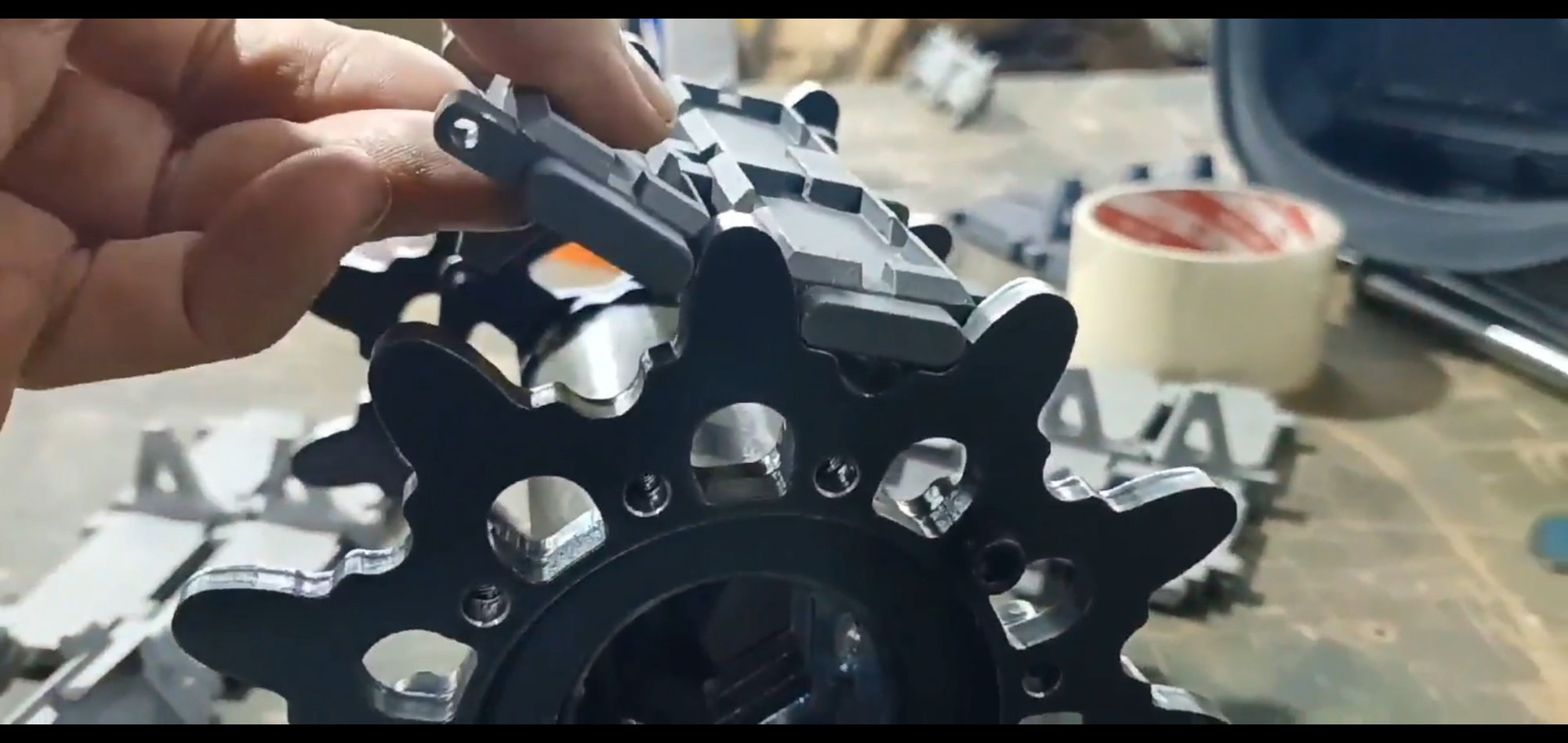
The material is bolt steel
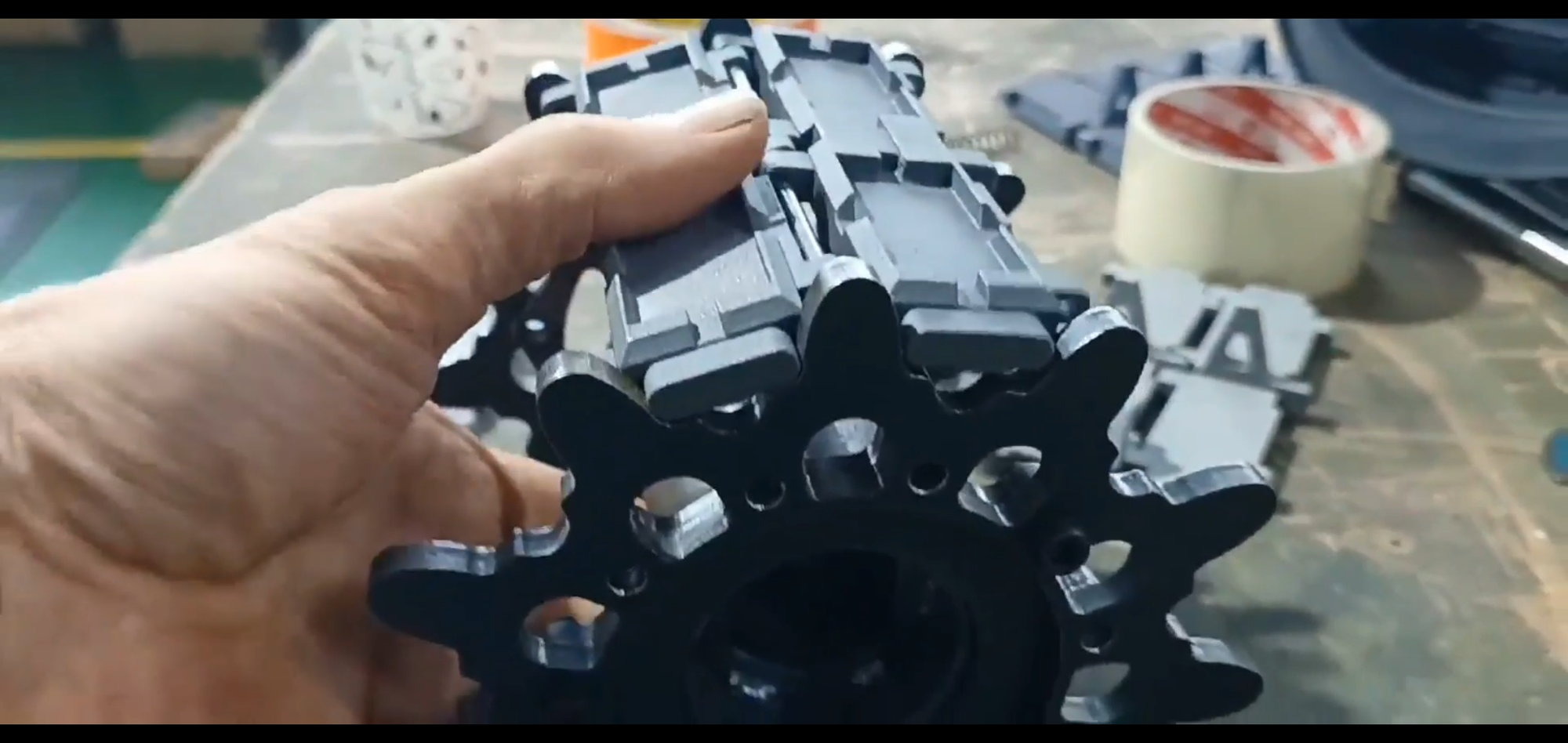
It's harder than normal casting
Its surface is grayed out by working with Sendblaster
Make holes and tap screws manually.
04-15-2023, 10:47 PM
#43
Thread Starter
A few days ago, a sample of a track made by outsourcing arrived and will be inspected
The sample of the casting track by outsourcing arrived the other day.
The connection is more natural and powerful
Check by hanging it on the sprocket that was made last time
Tightly operated to show less track deviations
The material is bolt steel
It's harder than normal casting
Its surface is grayed out by working with Sendblaster
Make holes and tap screws manually.
It's a 2022 k2 and it's a miniature version of the real track.
Looking at the case where the smaller-scale leopard tank has one hinge point, the wave shape appears
As a result of reviewing the driving behavior with a 3D printer sample, the shape of the waves was severe, so the casting method was changed
04-17-2023, 11:37 AM
#44
Thread Starter
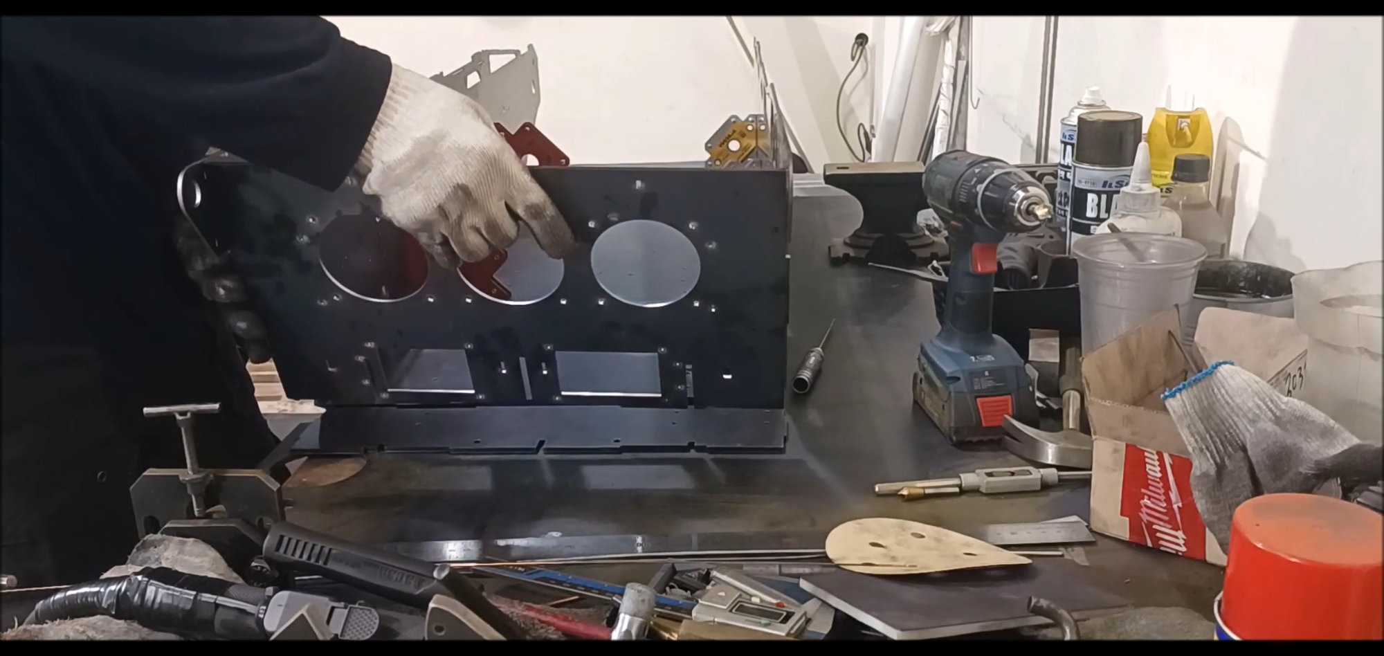
In this episode, body building begins. The body material is steel, and this work focuses on durability rather than detail, so it may have a slightly different shape from the actual vehicle.
Regards,
Young
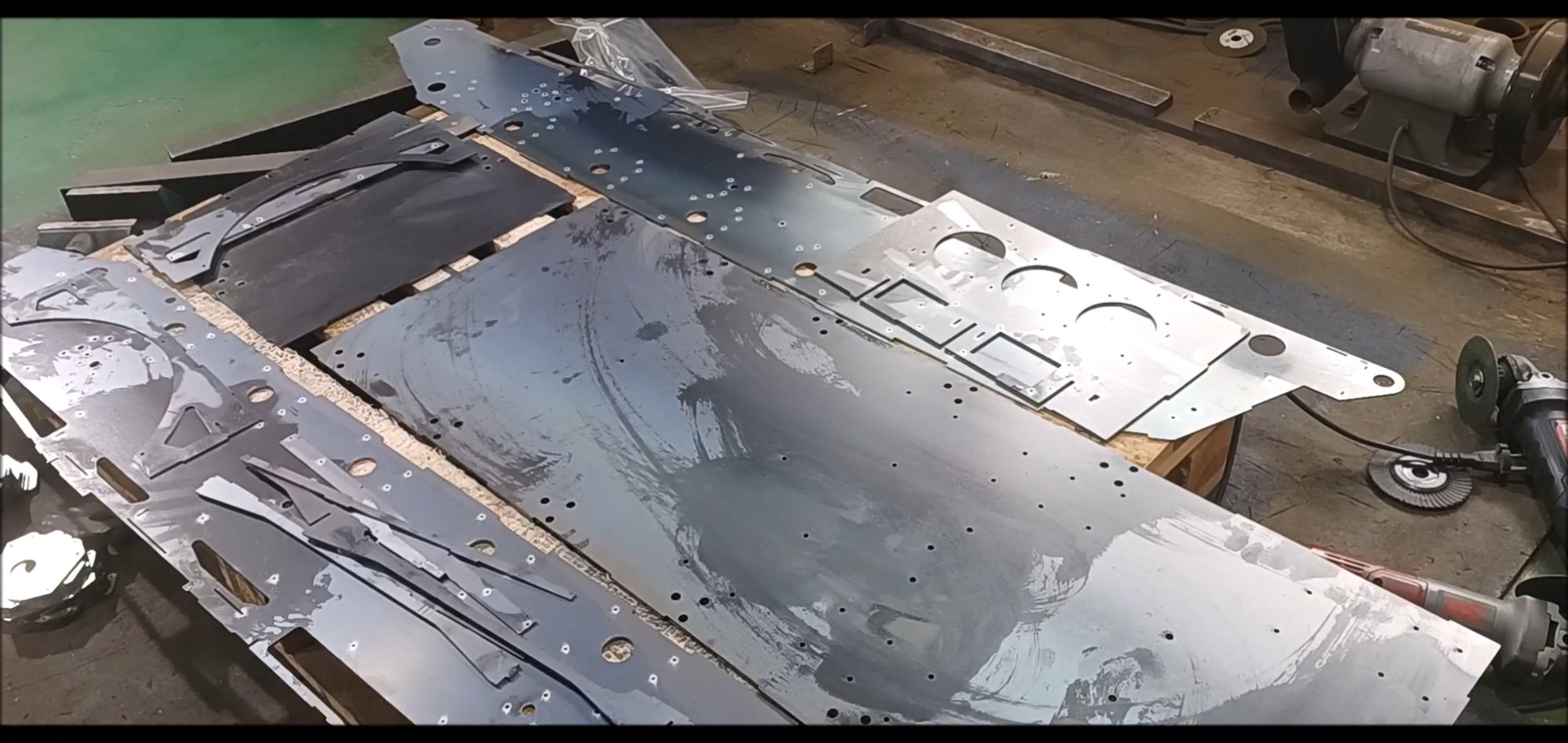
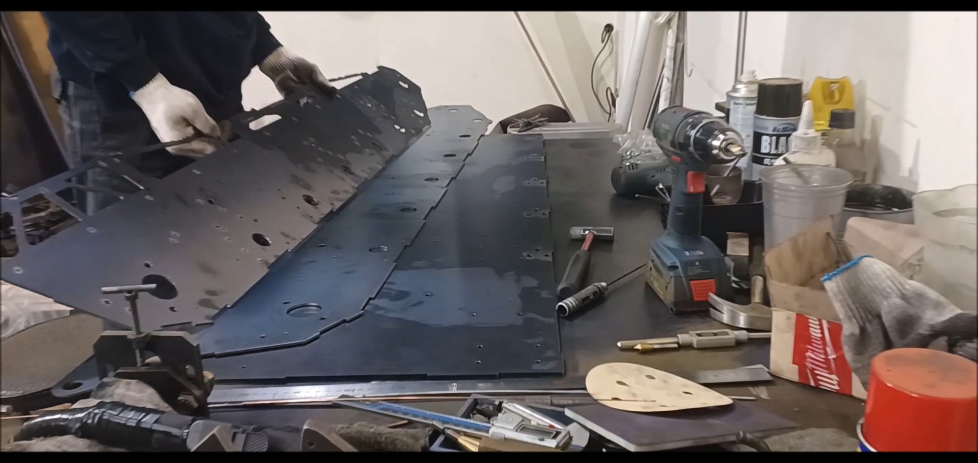
Transfer the pre-prepared body material to a temporary pallet for sink work and sanding work.
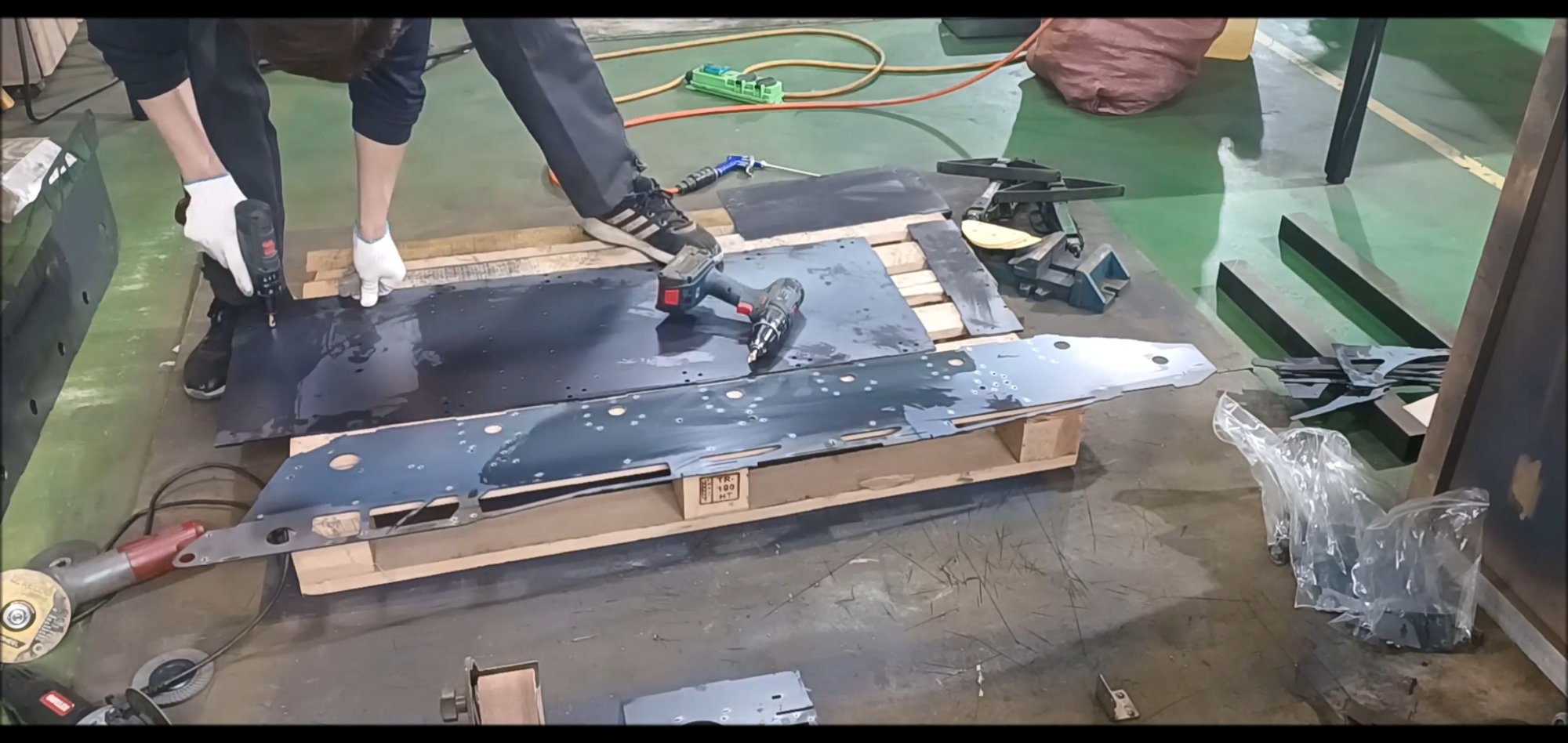
Every hole has a sink
Sink all holes without omission
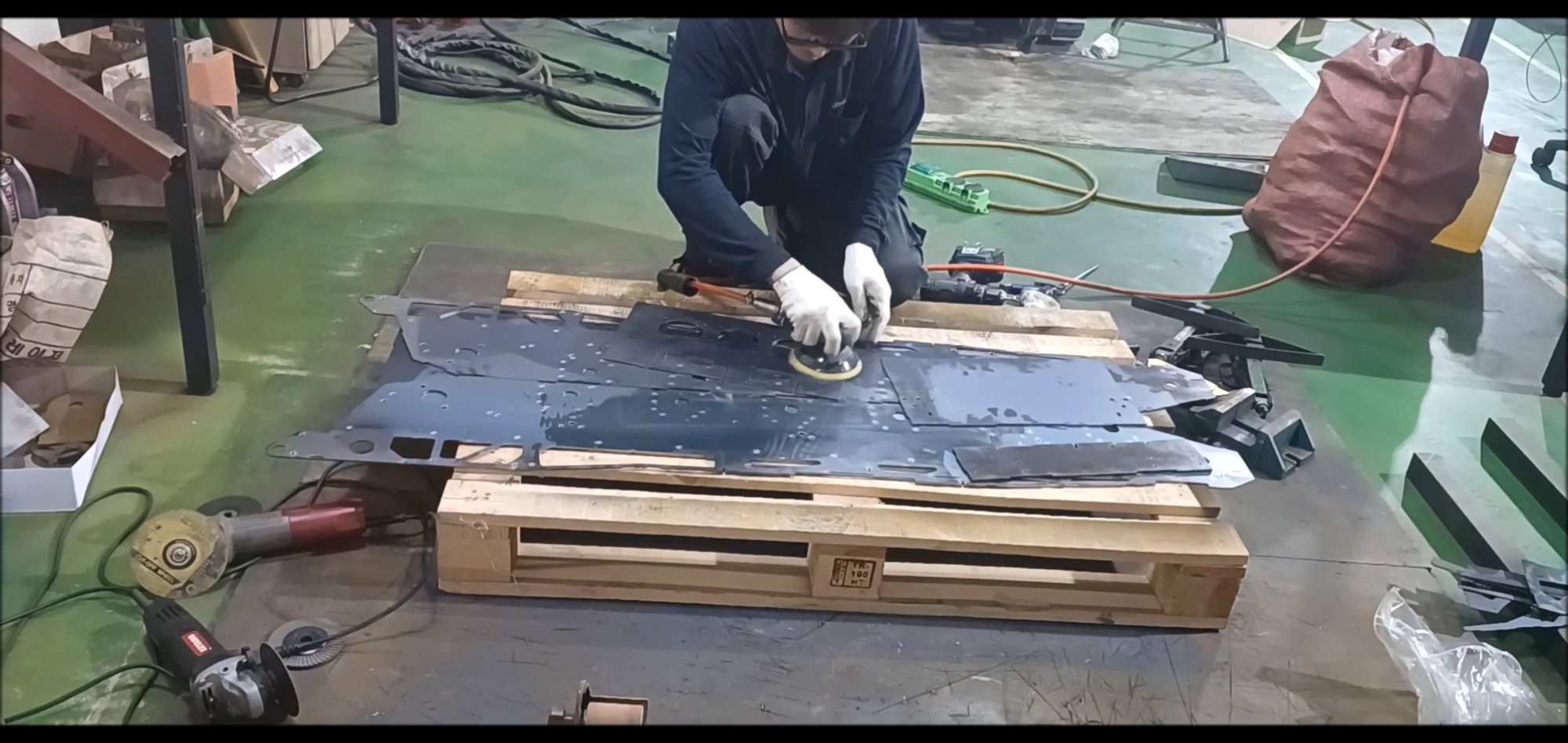
Sink operation followed by a sanding operation on the surface
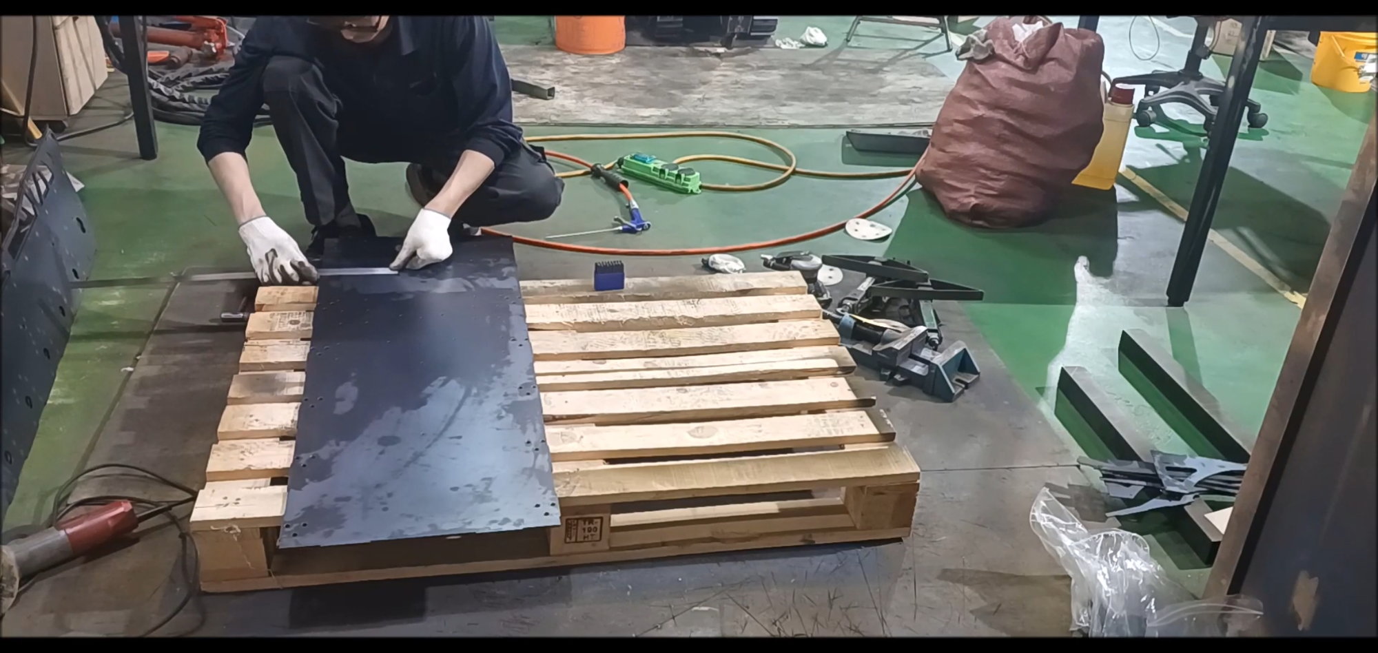
K2 Black Panther is different from left to right, so it makes a clear distinction
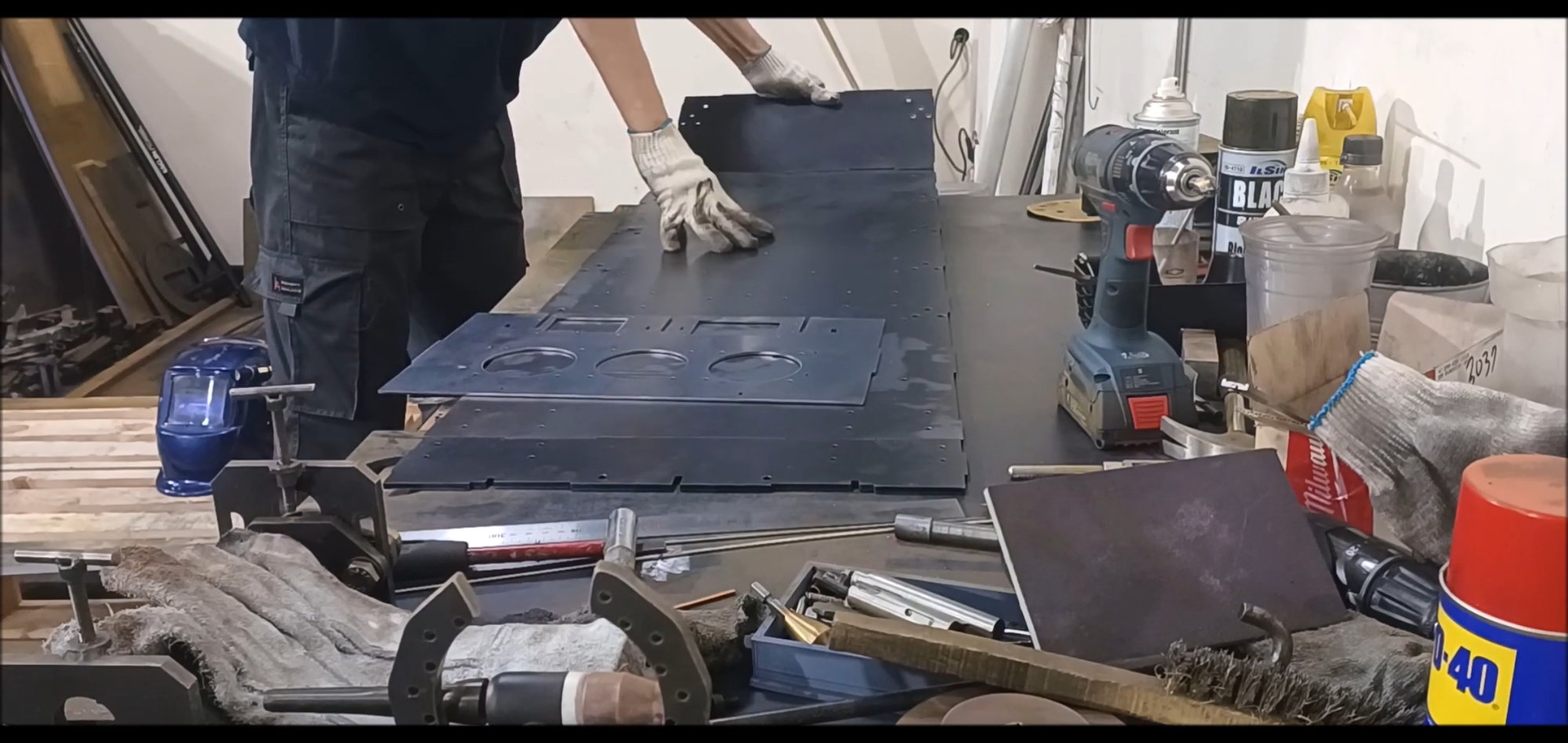
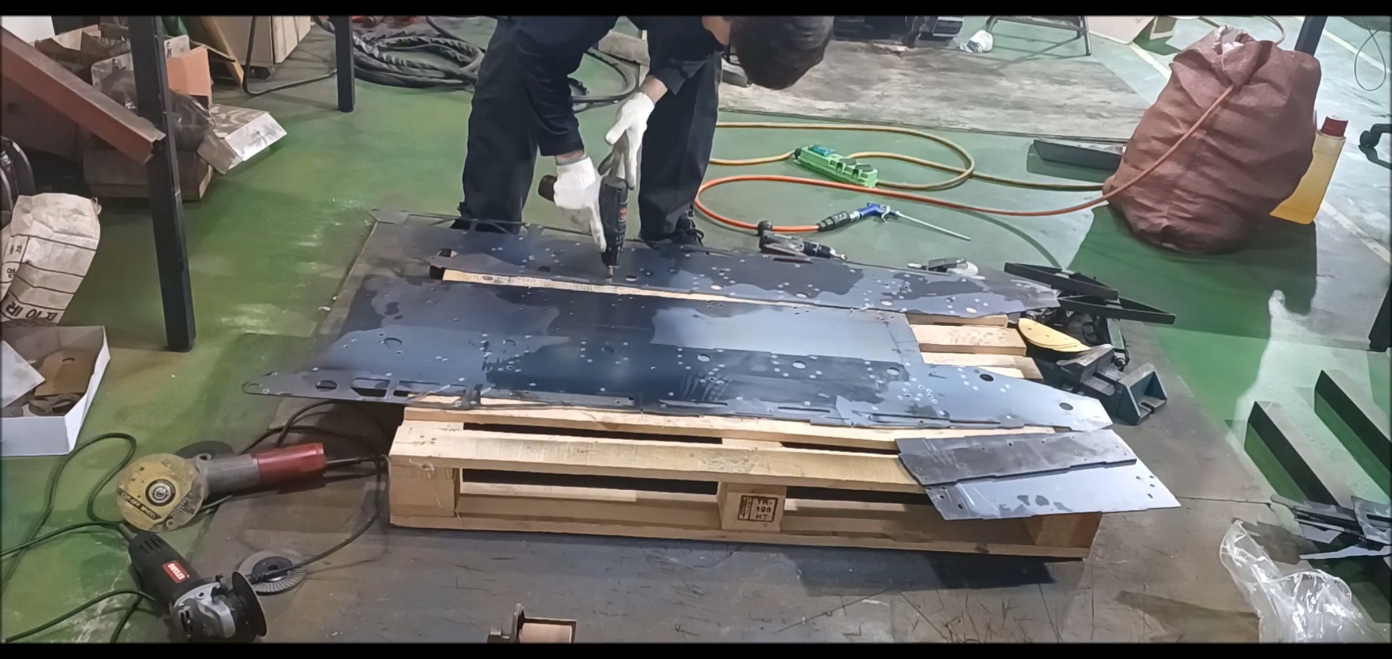
Move to workbench to verify configuration
Bolted the bottom of the body to reinforce the stress on the hole
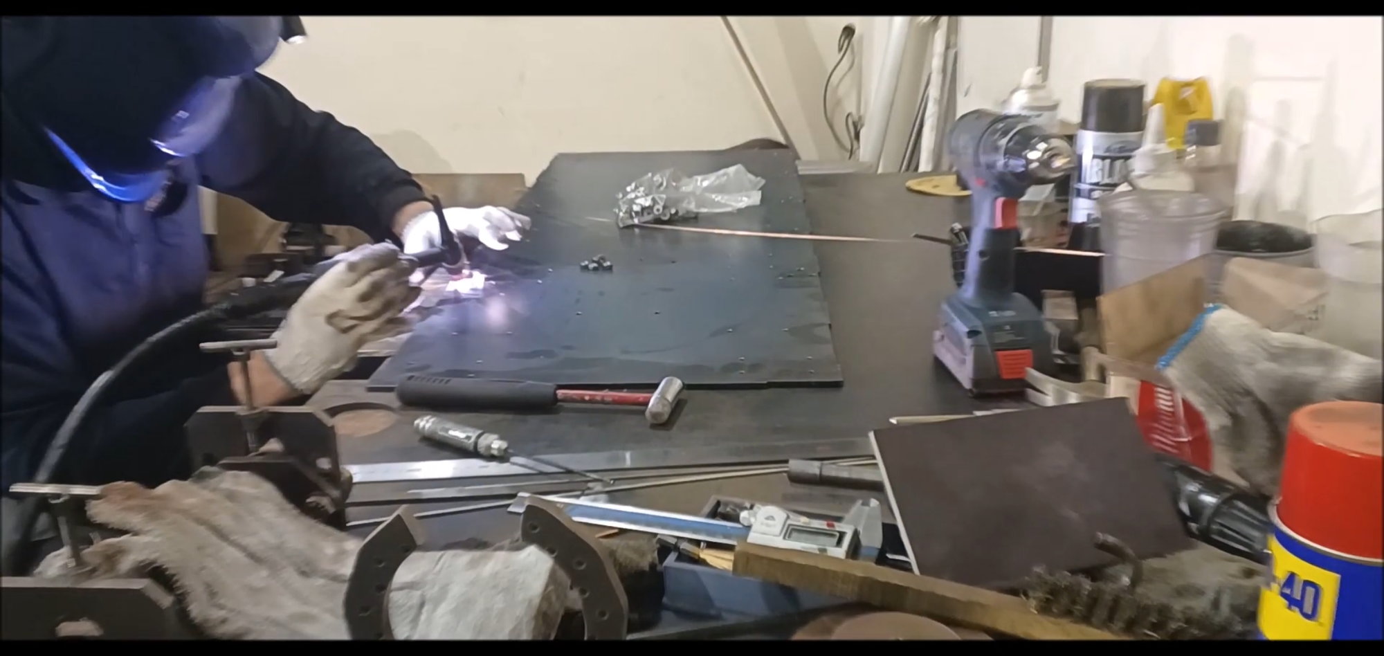
A bolt is first welded by temporary welding
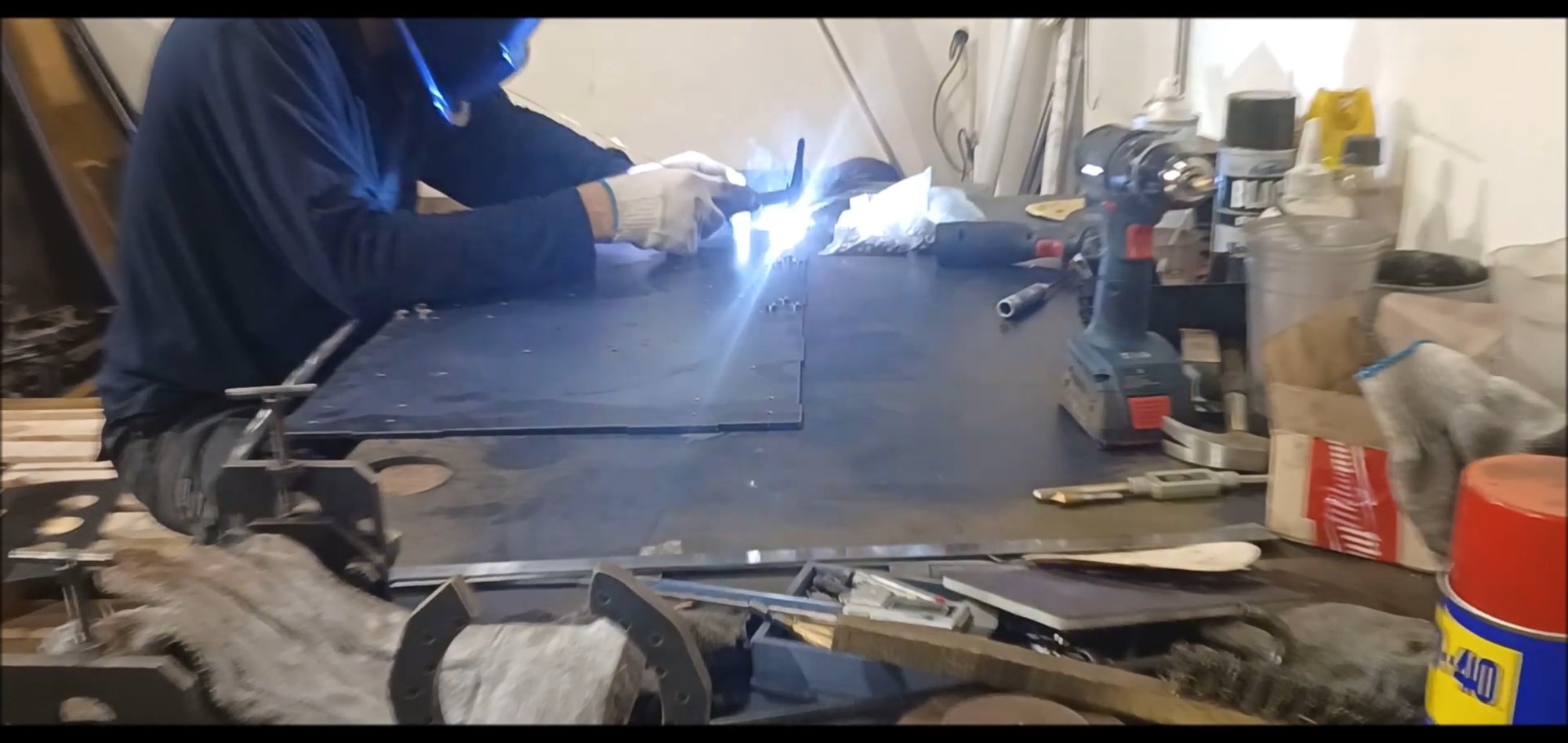
Bolt reinforcement is a work for durability rather than detail, which is different from real vehicles
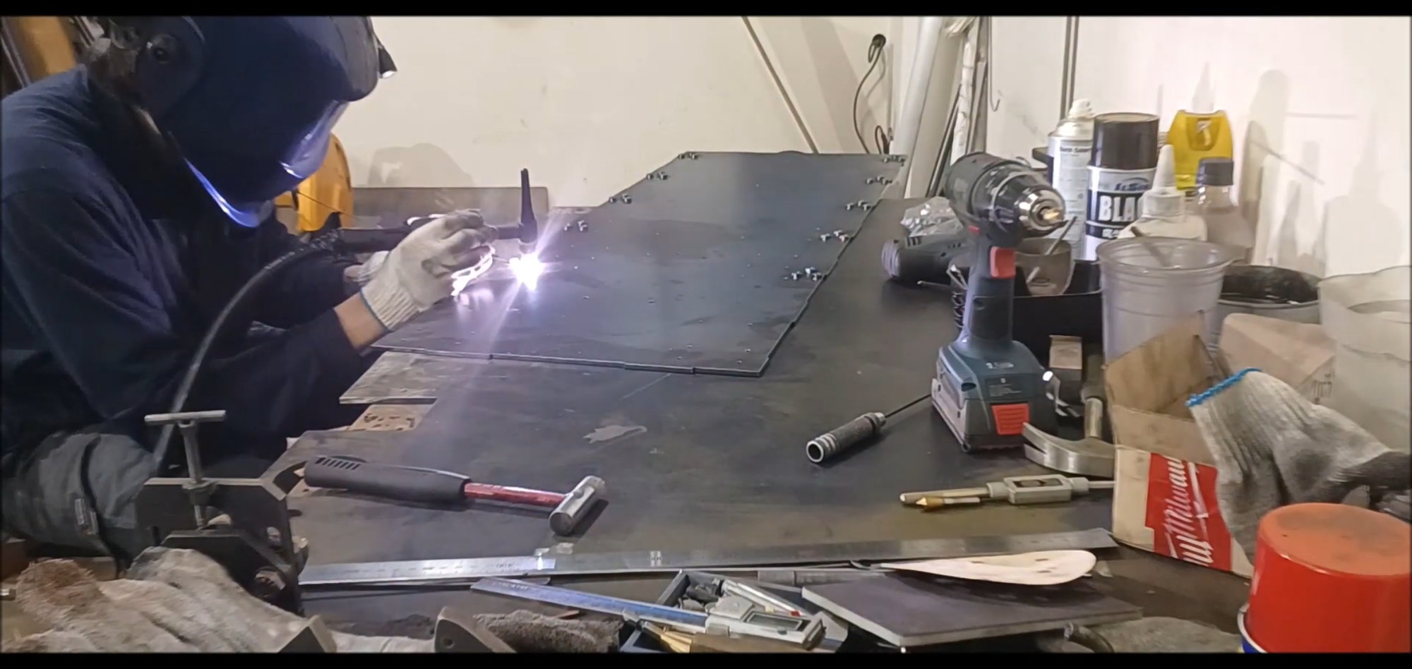
Use a welding rod to weld reinforcement
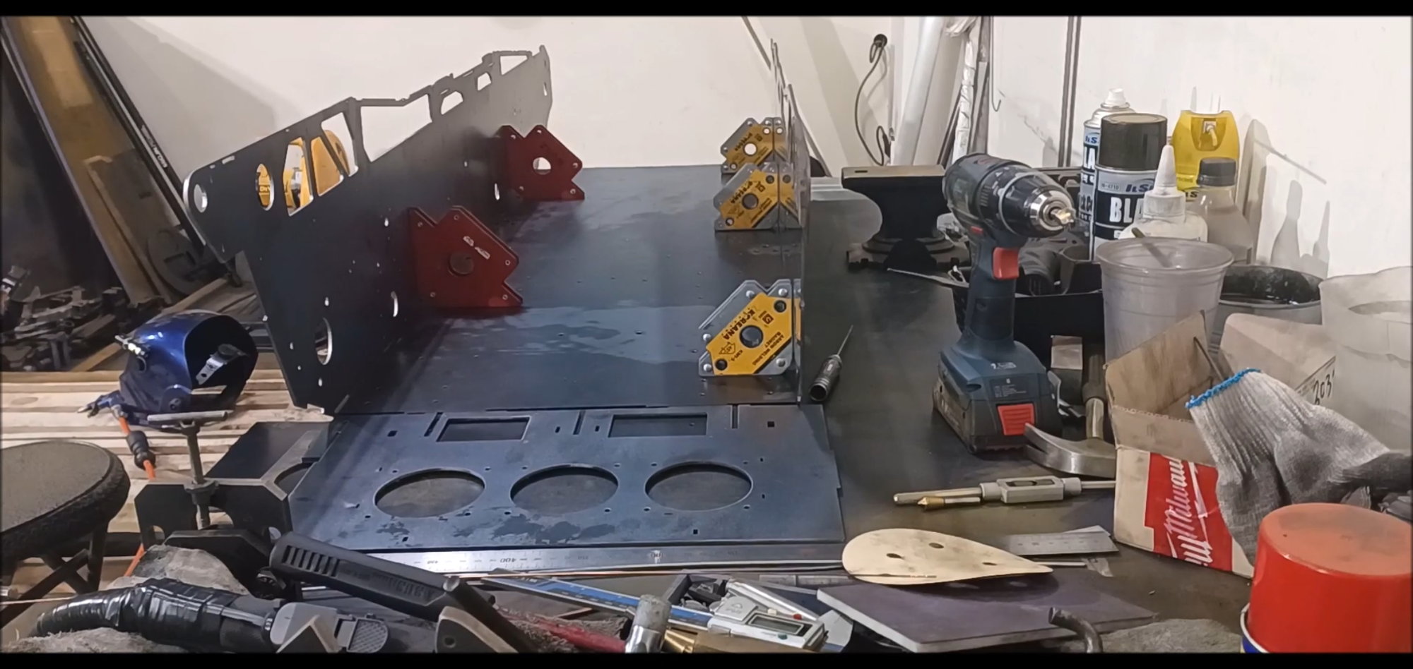
Install the side of the vehicle separately
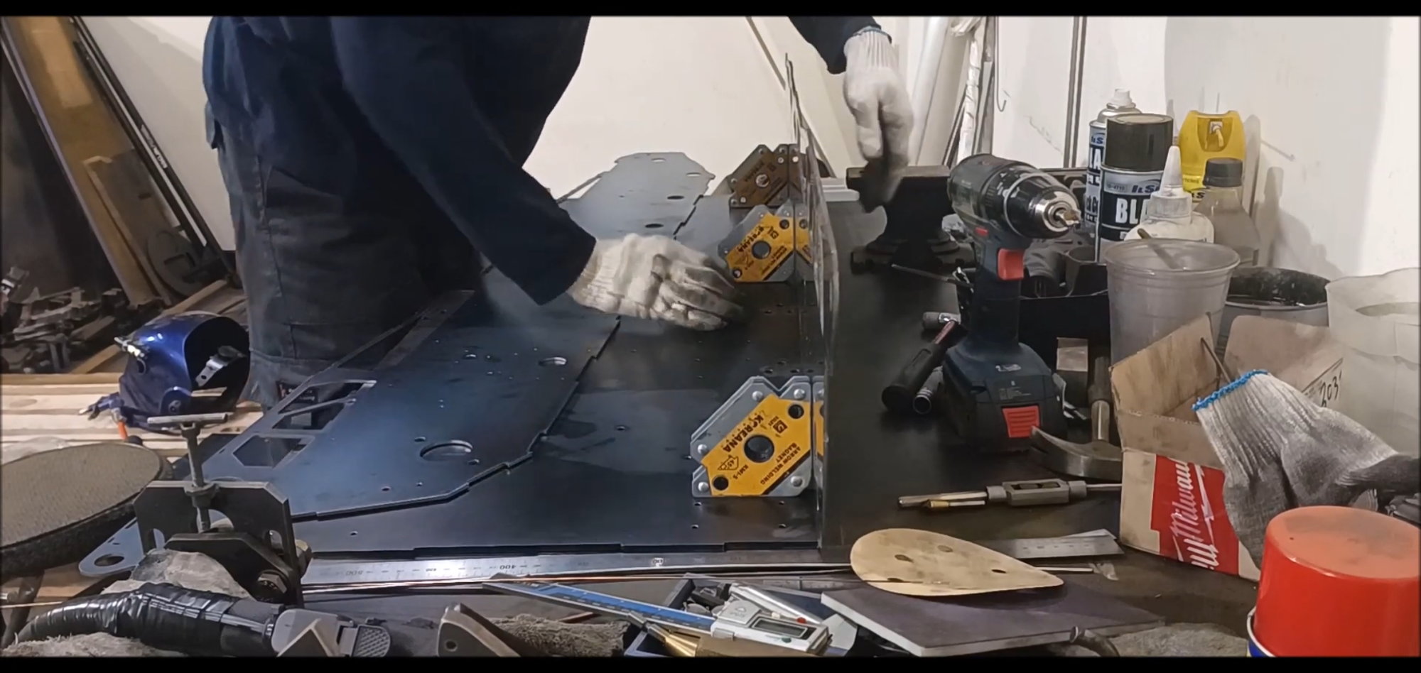
Construct geometry temporarily using a right angle magnet retainer
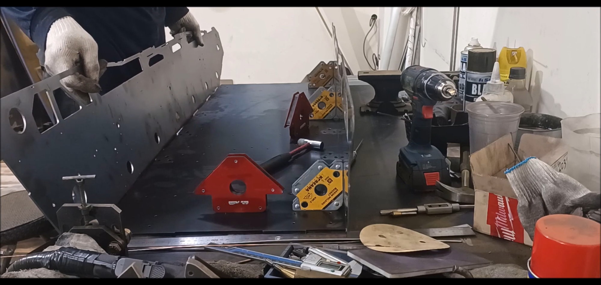
Construct geometry temporarily using a right angle magnet retainer
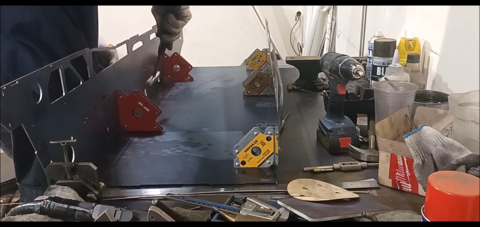
Hold the right angle and position
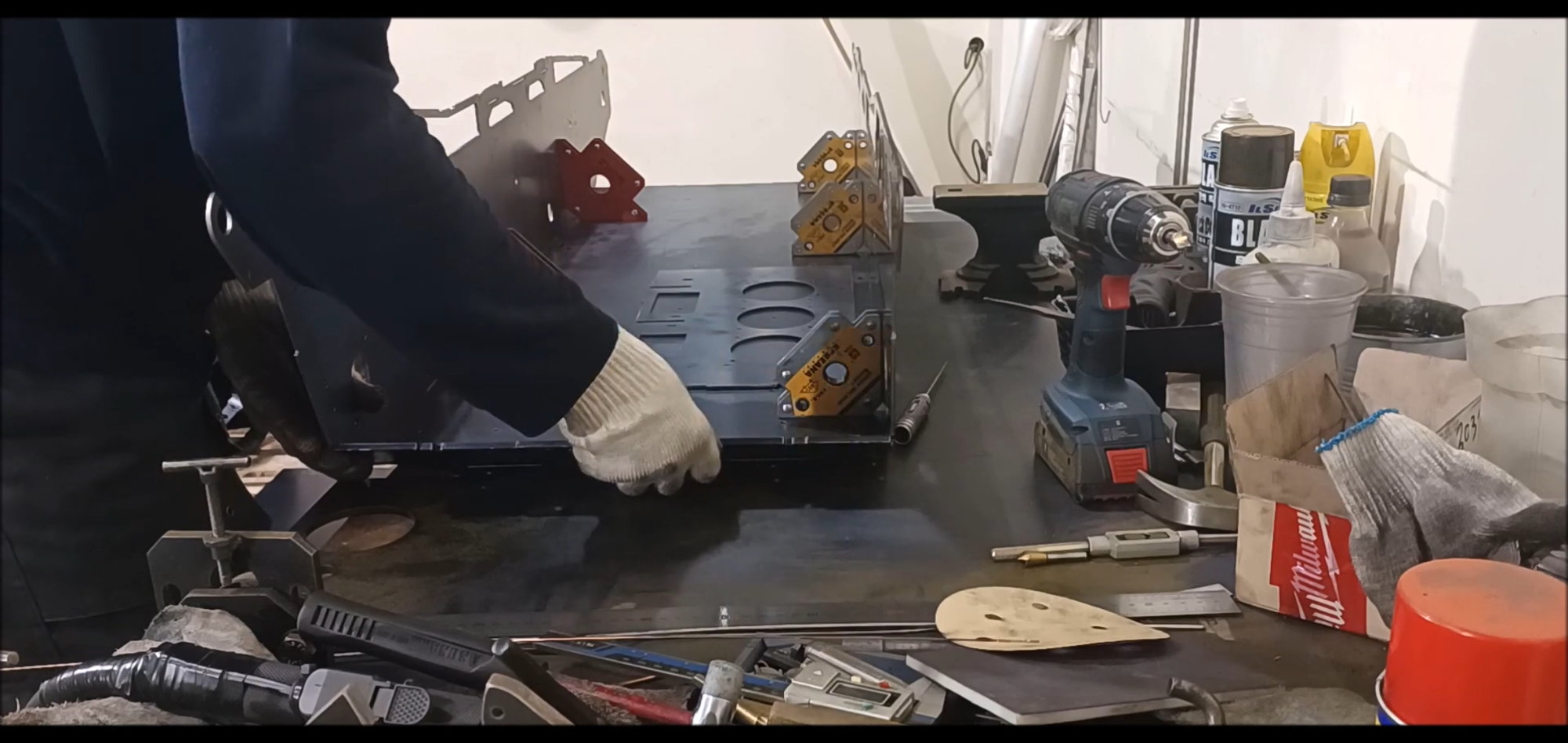
Check the front and rear body material
Check the front and rear body material
The gearbox must be manufactured first before the body can be welded
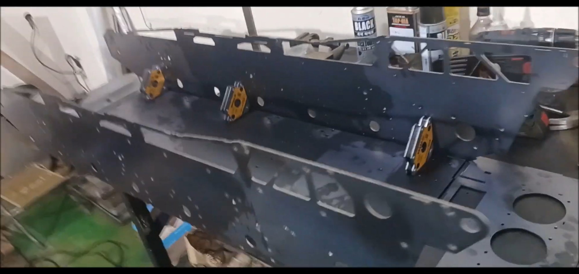
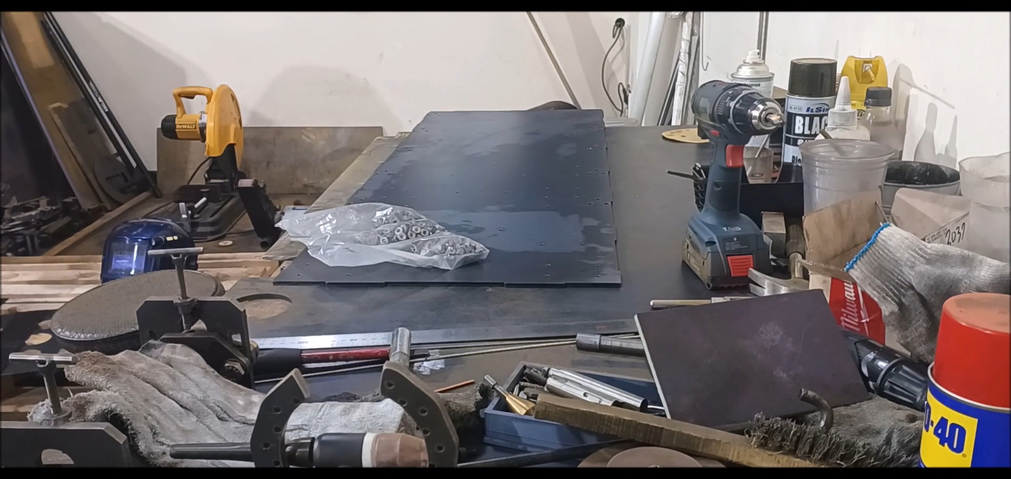
This week's work includes temporary configuration of features
Continue in the next episode.....
Regards,
Young
Transfer the pre-prepared body material to a temporary pallet for sink work and sanding work.
Every hole has a sink
Sink all holes without omission
Sink operation followed by a sanding operation on the surface
K2 Black Panther is different from left to right, so it makes a clear distinction
Move to workbench to verify configuration
Bolted the bottom of the body to reinforce the stress on the hole
A bolt is first welded by temporary welding
Bolt reinforcement is a work for durability rather than detail, which is different from real vehicles
Use a welding rod to weld reinforcement
Install the side of the vehicle separately
Construct geometry temporarily using a right angle magnet retainer
Construct geometry temporarily using a right angle magnet retainer
Hold the right angle and position
Check the front and rear body material
Check the front and rear body material
The gearbox must be manufactured first before the body can be welded
This week's work includes temporary configuration of features
Continue in the next episode.....
Last edited by PE YOUNG; 04-17-2023 at 02:20 PM.
The following users liked this post:
tankme (04-17-2023)
04-23-2023, 12:58 PM
#45
Thread Starter
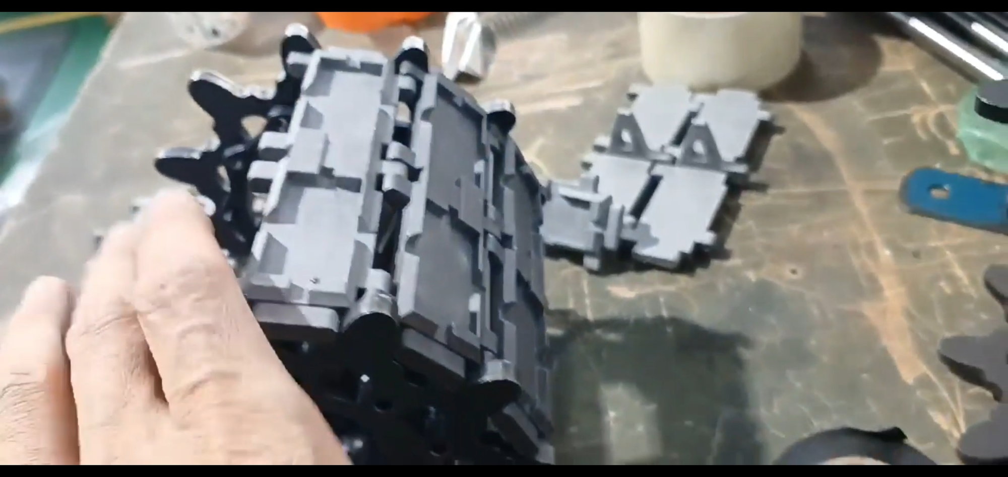
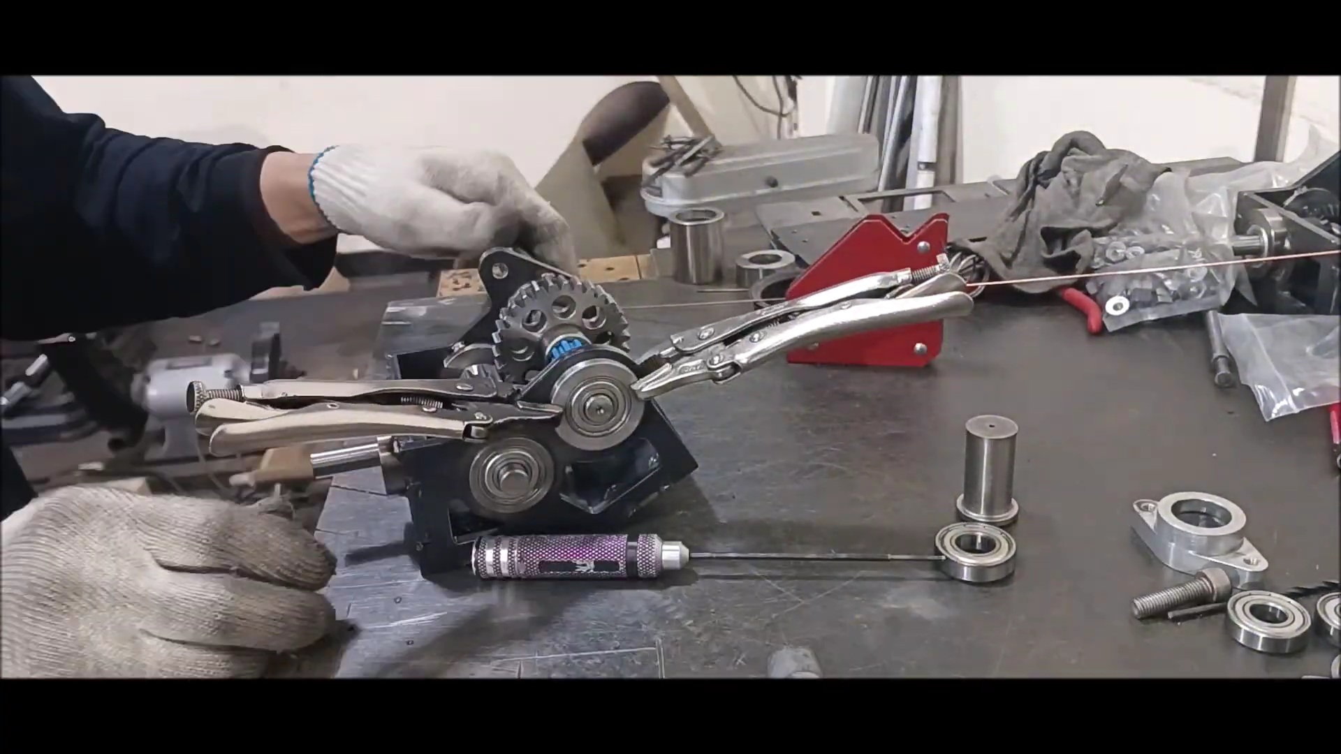
In this episode, a gear box for driving a sprocket will be manufactured, fixed to the left and right sides of the rear of the vehicle, and the gear for the turret in the middle of the vehicle body will be fixed
Regards,
Young
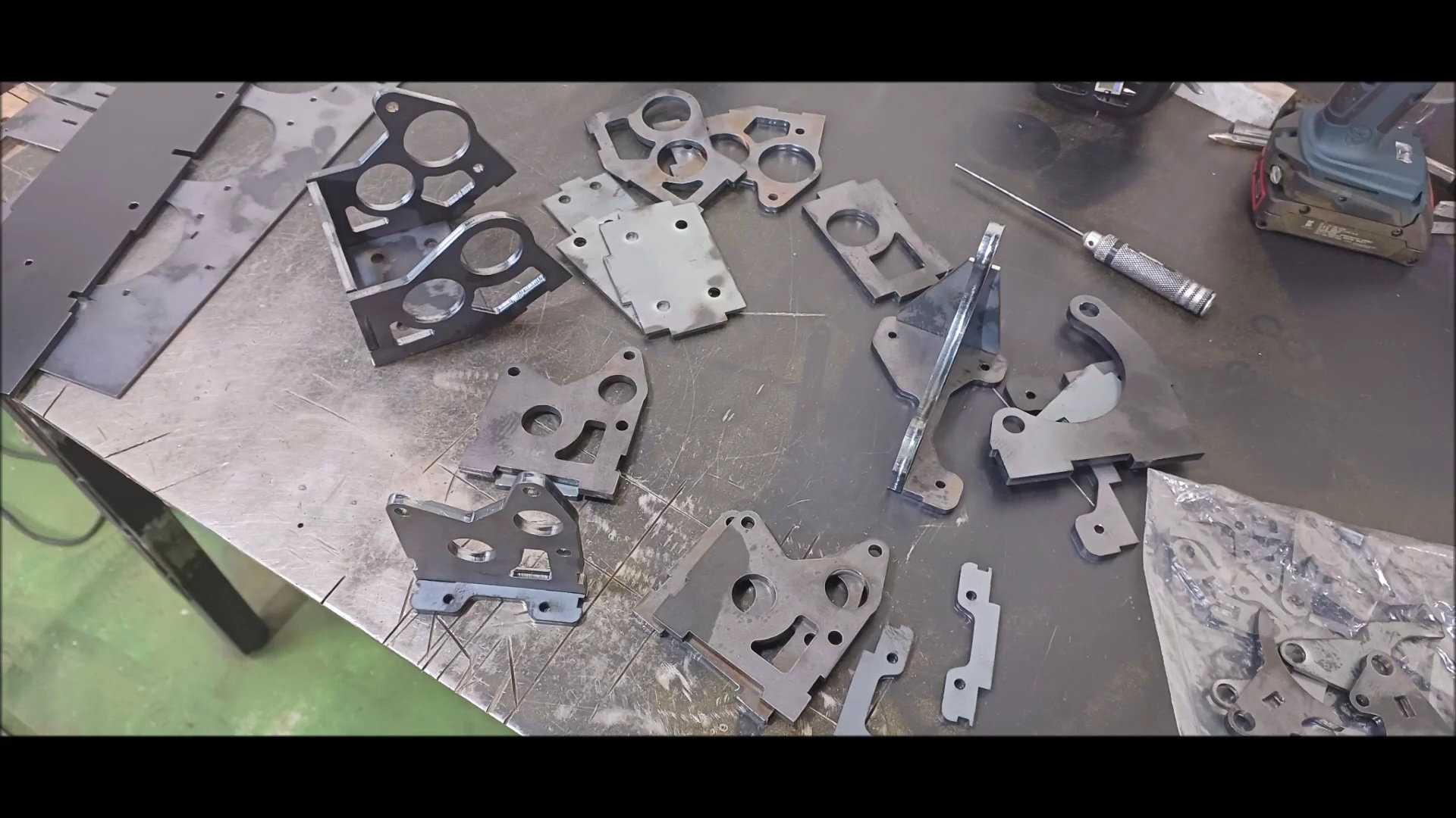
Laser-cut gearbox housing
Check the number of bearing boxes and shafts required
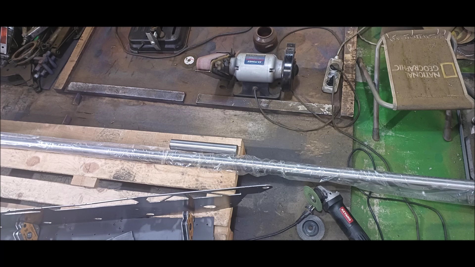
Get ready for the round bar
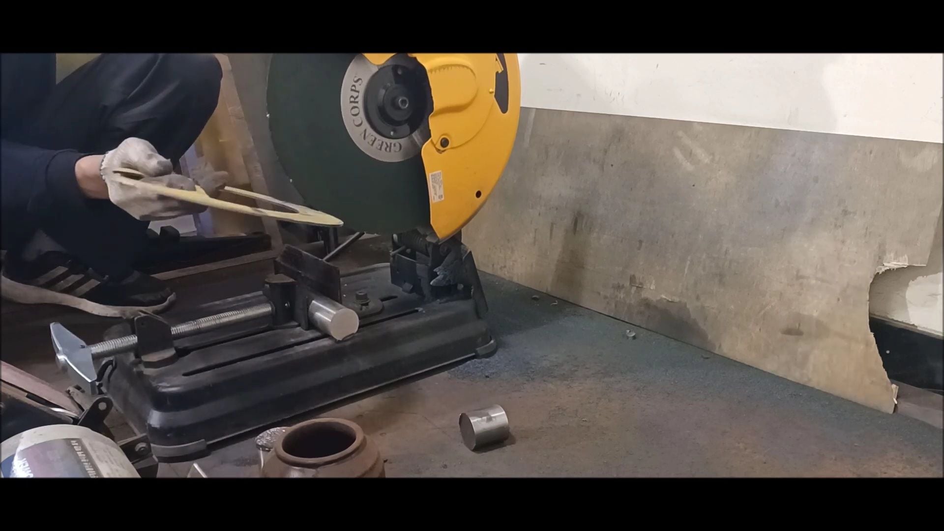
Effective cutting can be done if there is a gap groove on the cutting machine blade
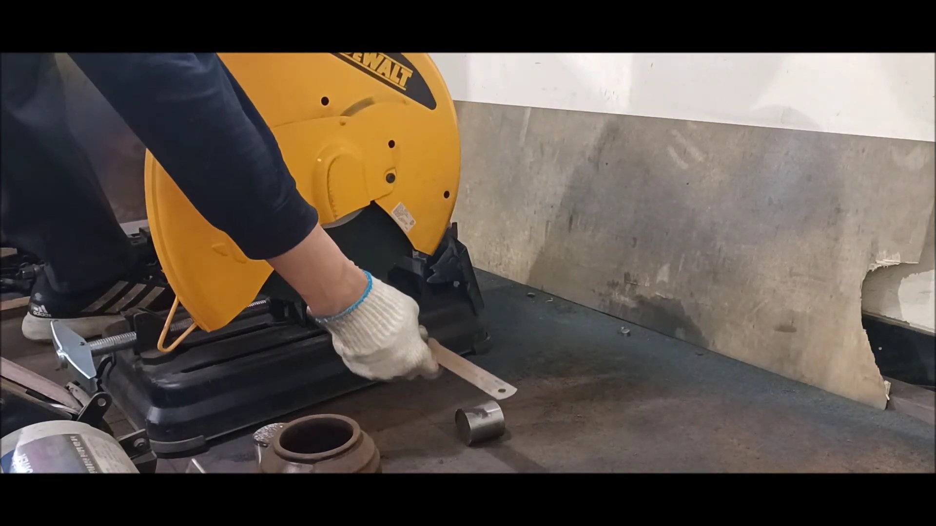
Measure the length of the cut using a steel ruler
round bar cutting
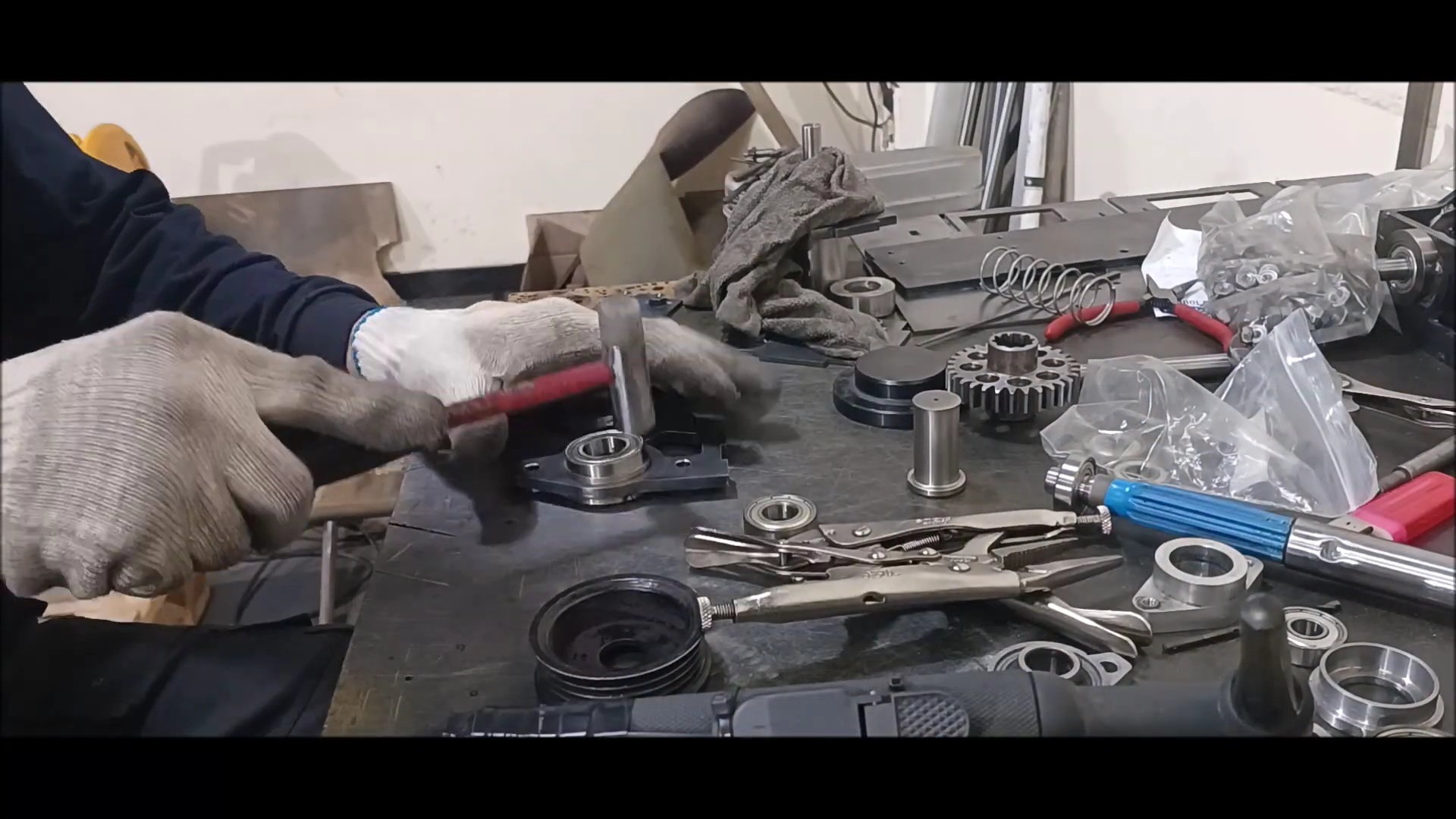
Bearing Housing Shelf Machine Work - 1
Bearing Housing Shelf Machine Work - 2
Bearing Housing Shelf Machine Work - 3
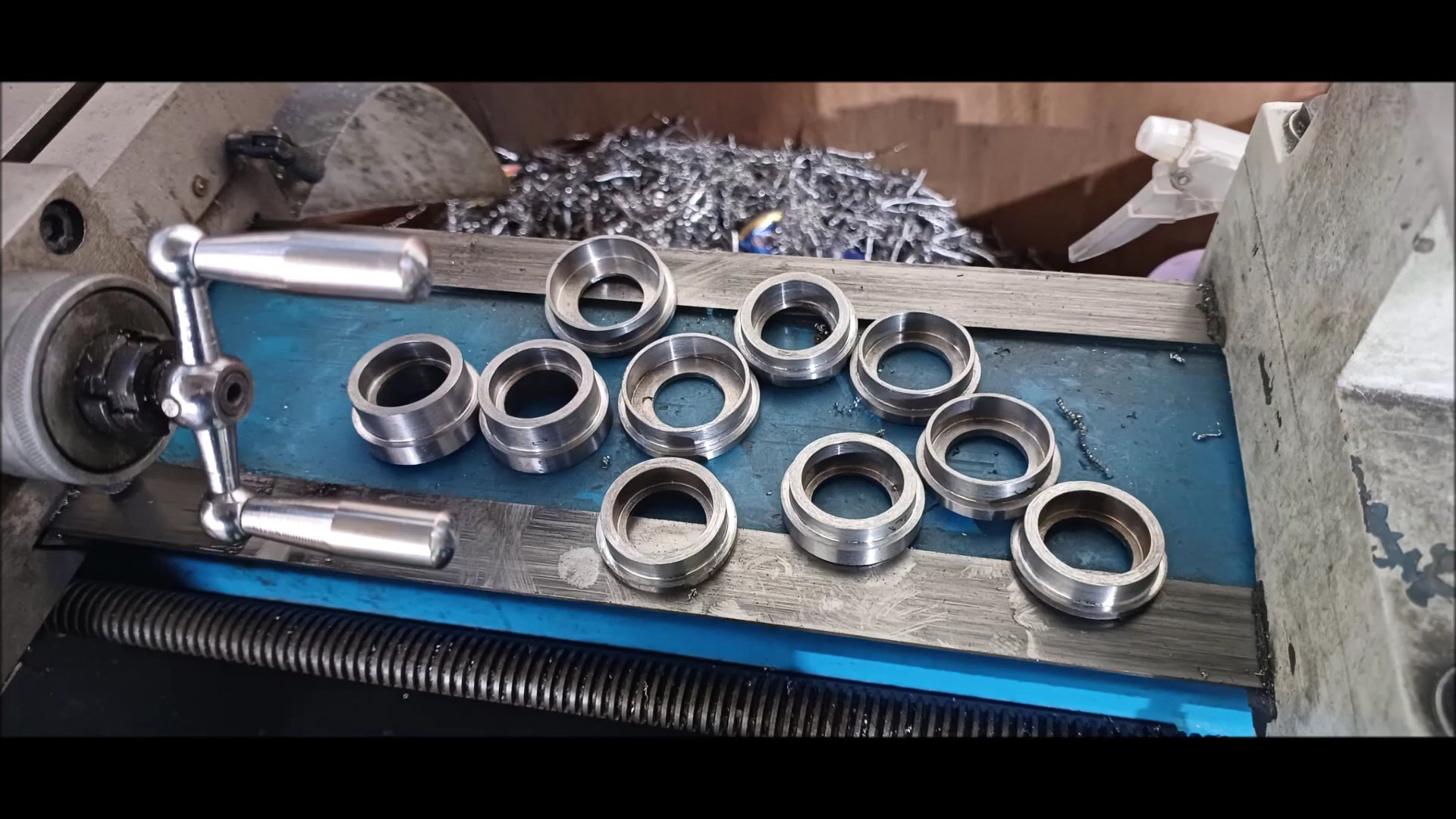
Bearing Housing Shelf Machine Work - 4
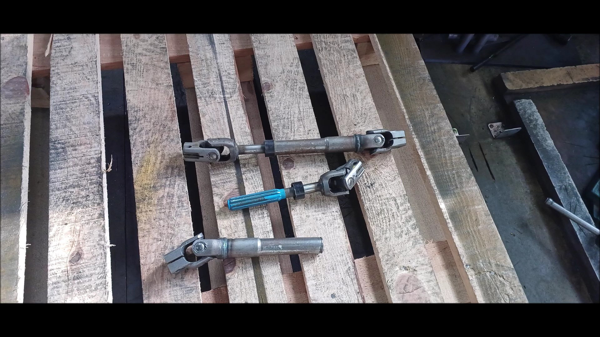
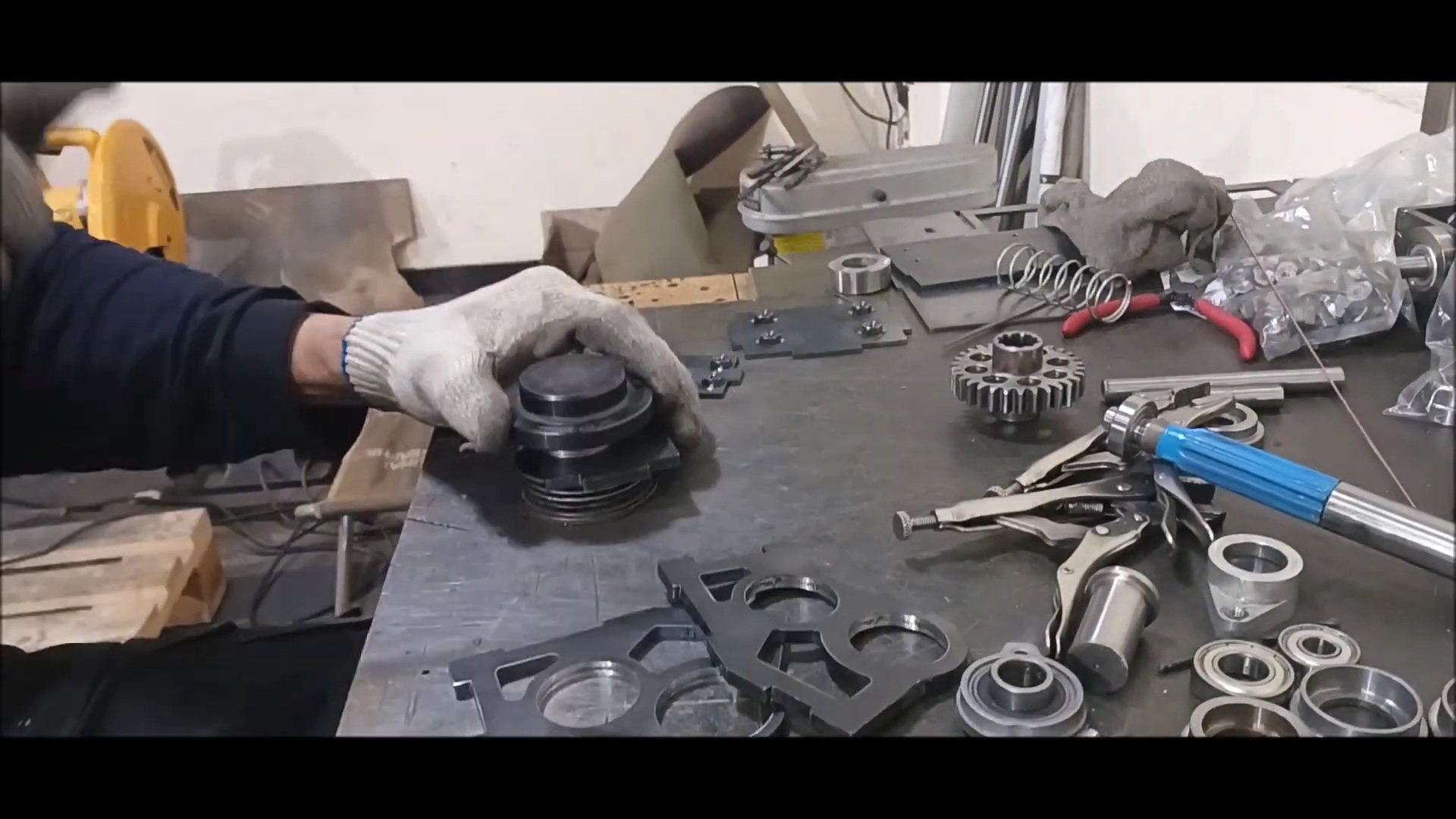
Preparation of constant speed joints from vehicle
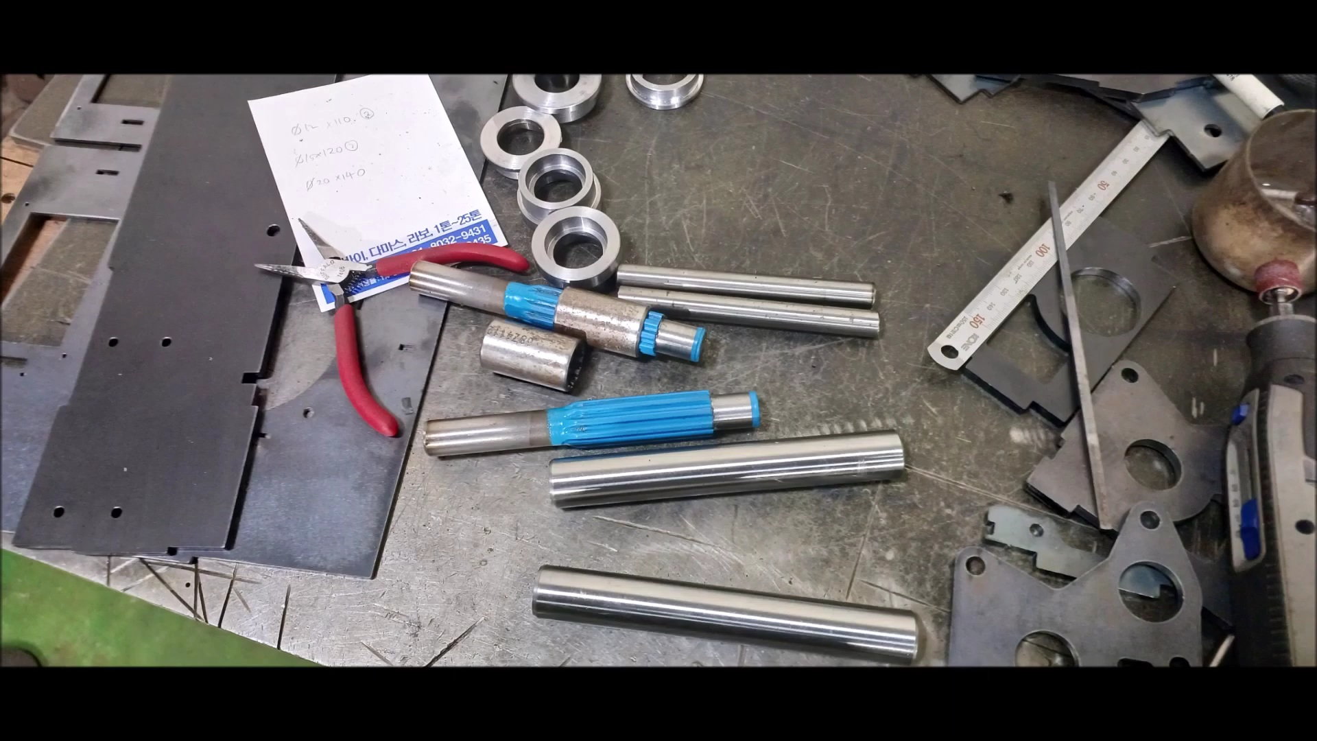
use a spline
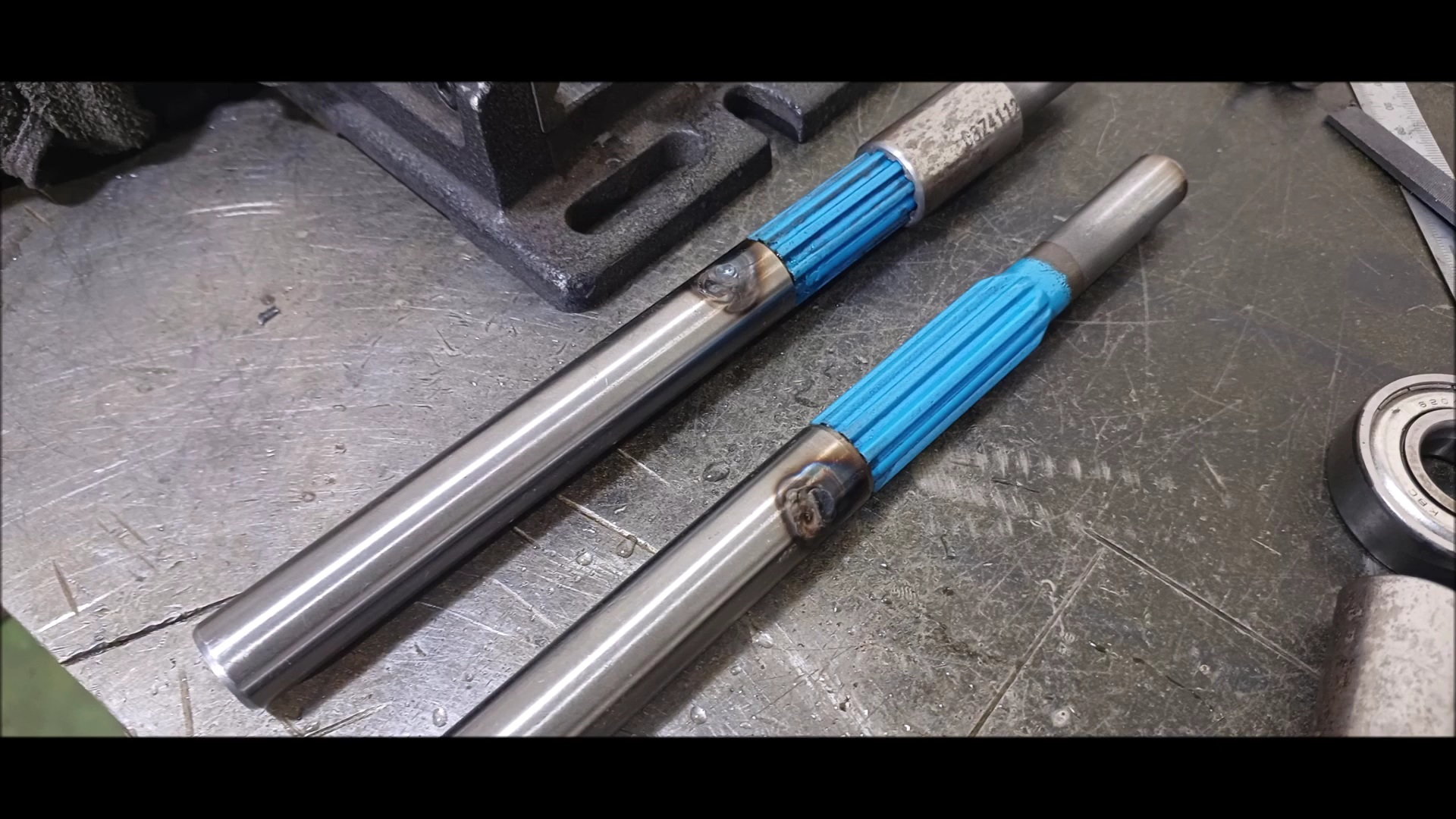
Round bar and welding for cut spline and drive shaft
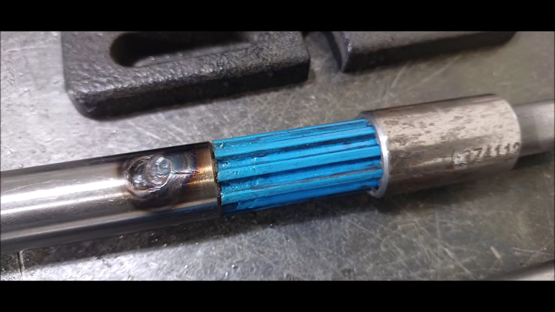
a welded figure
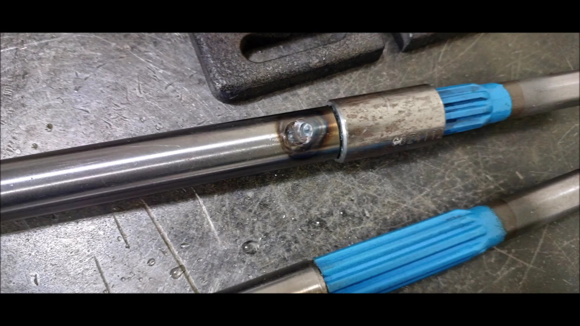
Thermal deformation occurred while welding the spline coating part, but there is no problem with the operation of the snivel
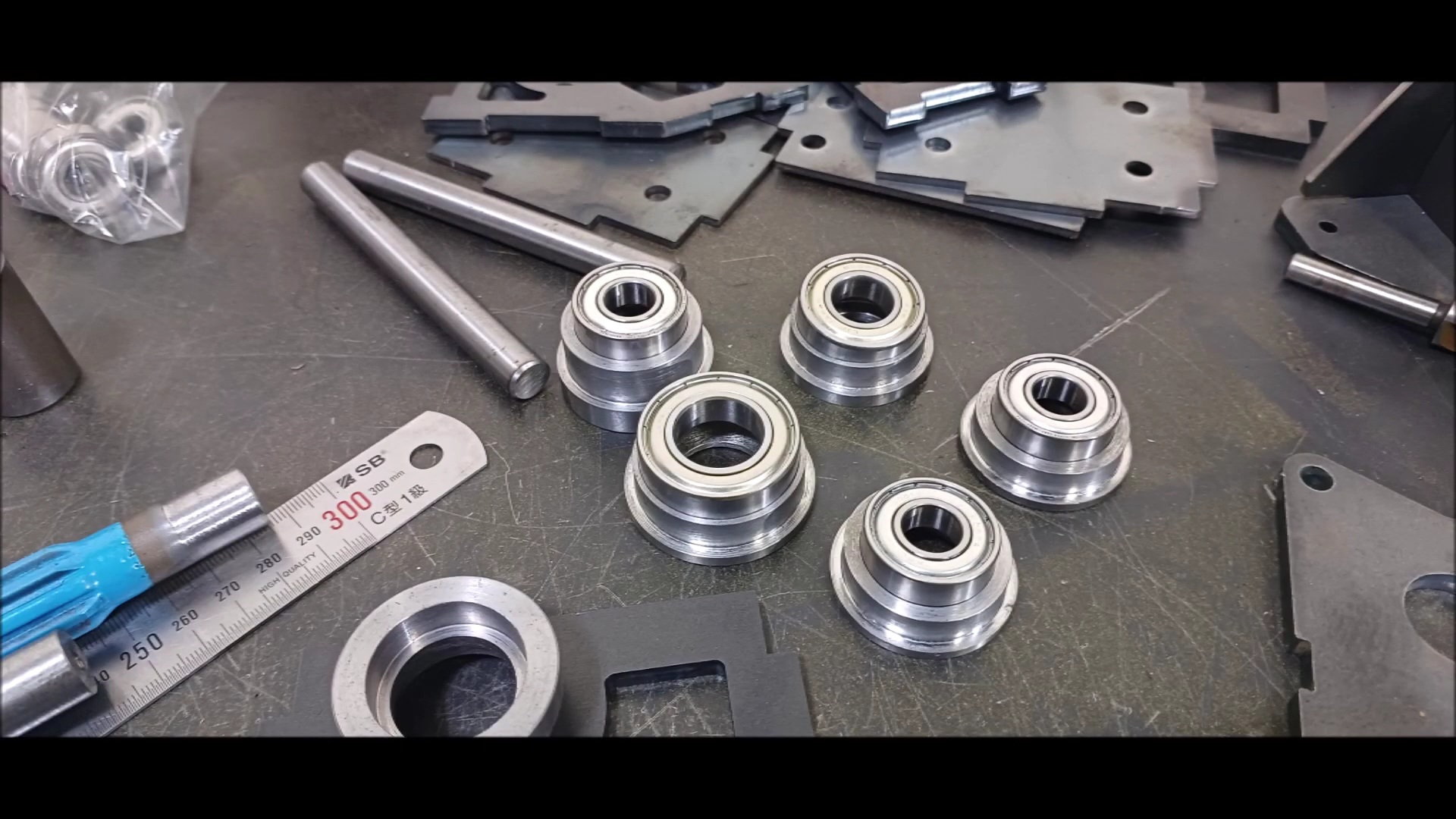
Manufactured bearing housing
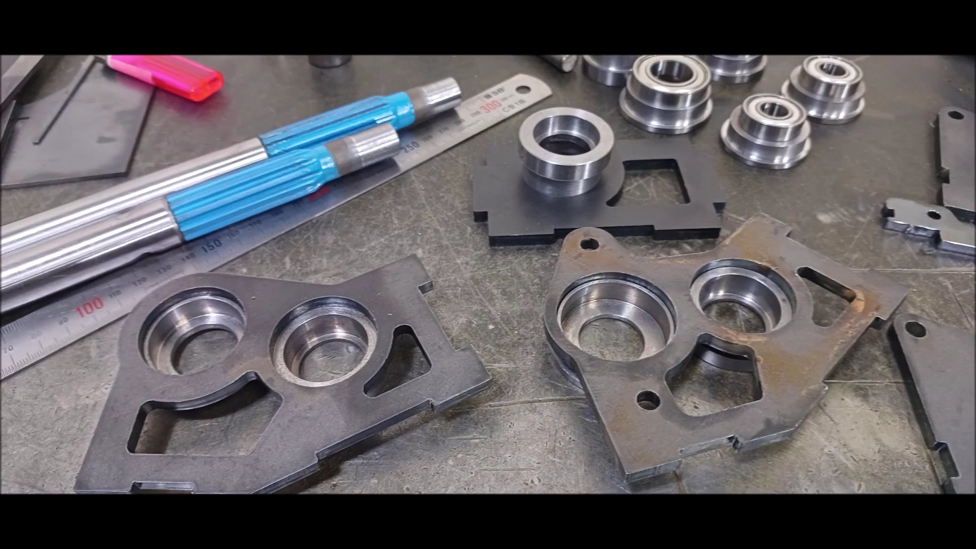
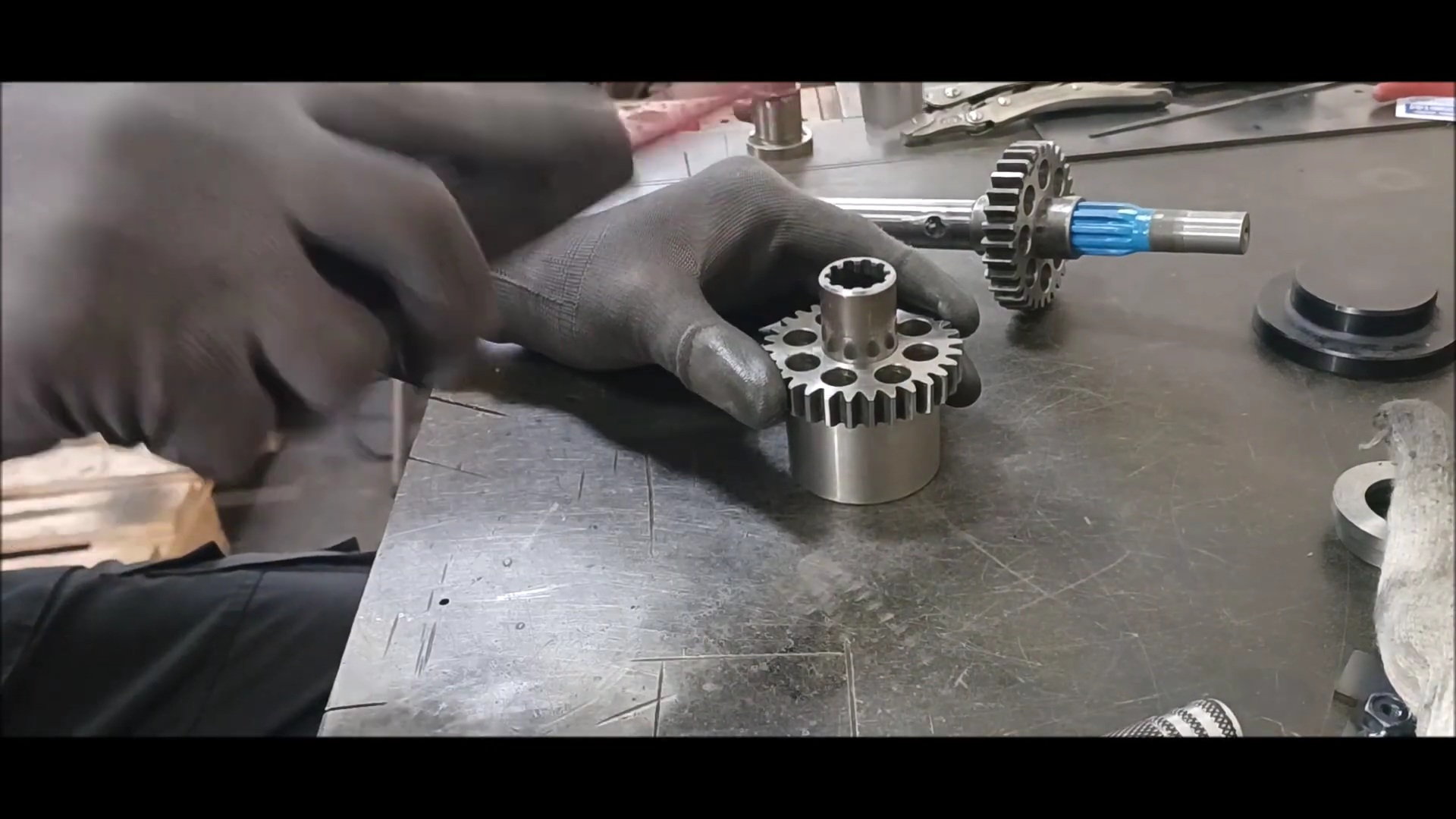
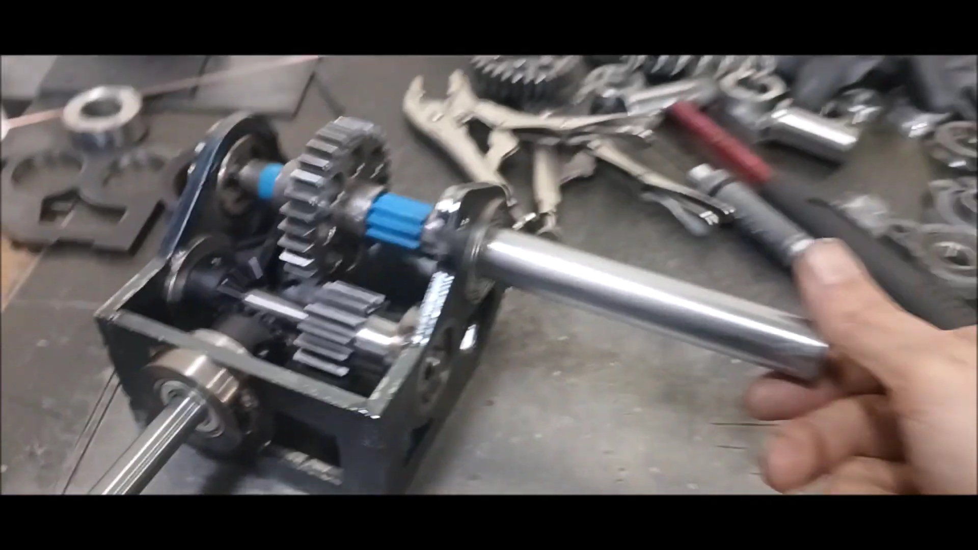
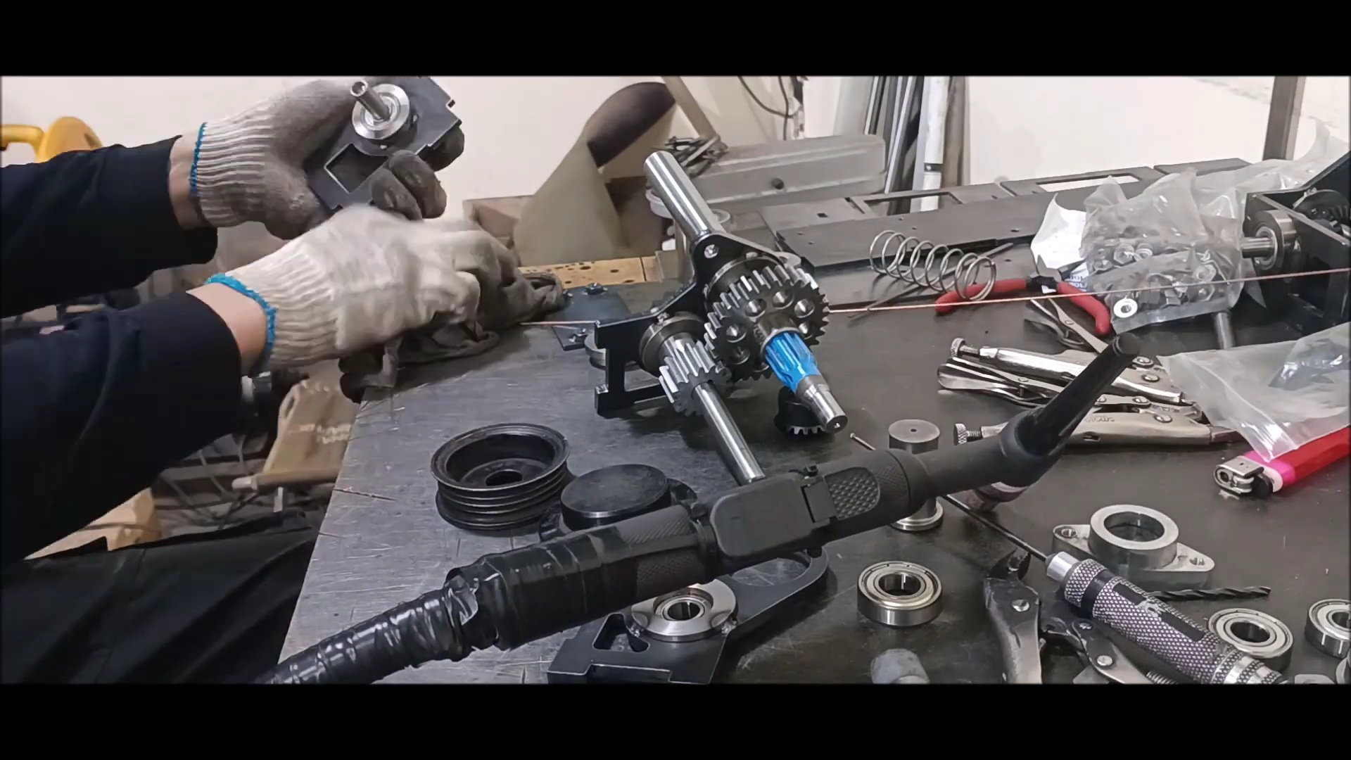
Gearbox assembly
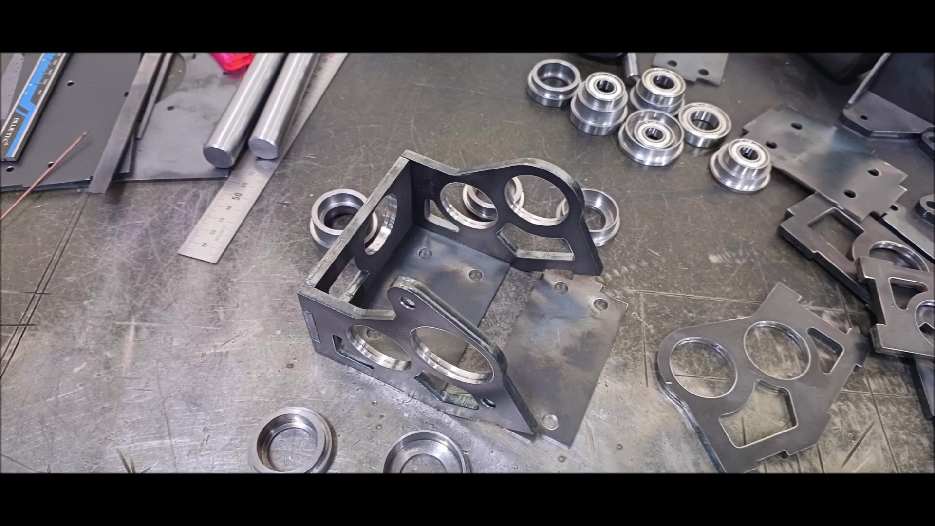
Gearbox assembly
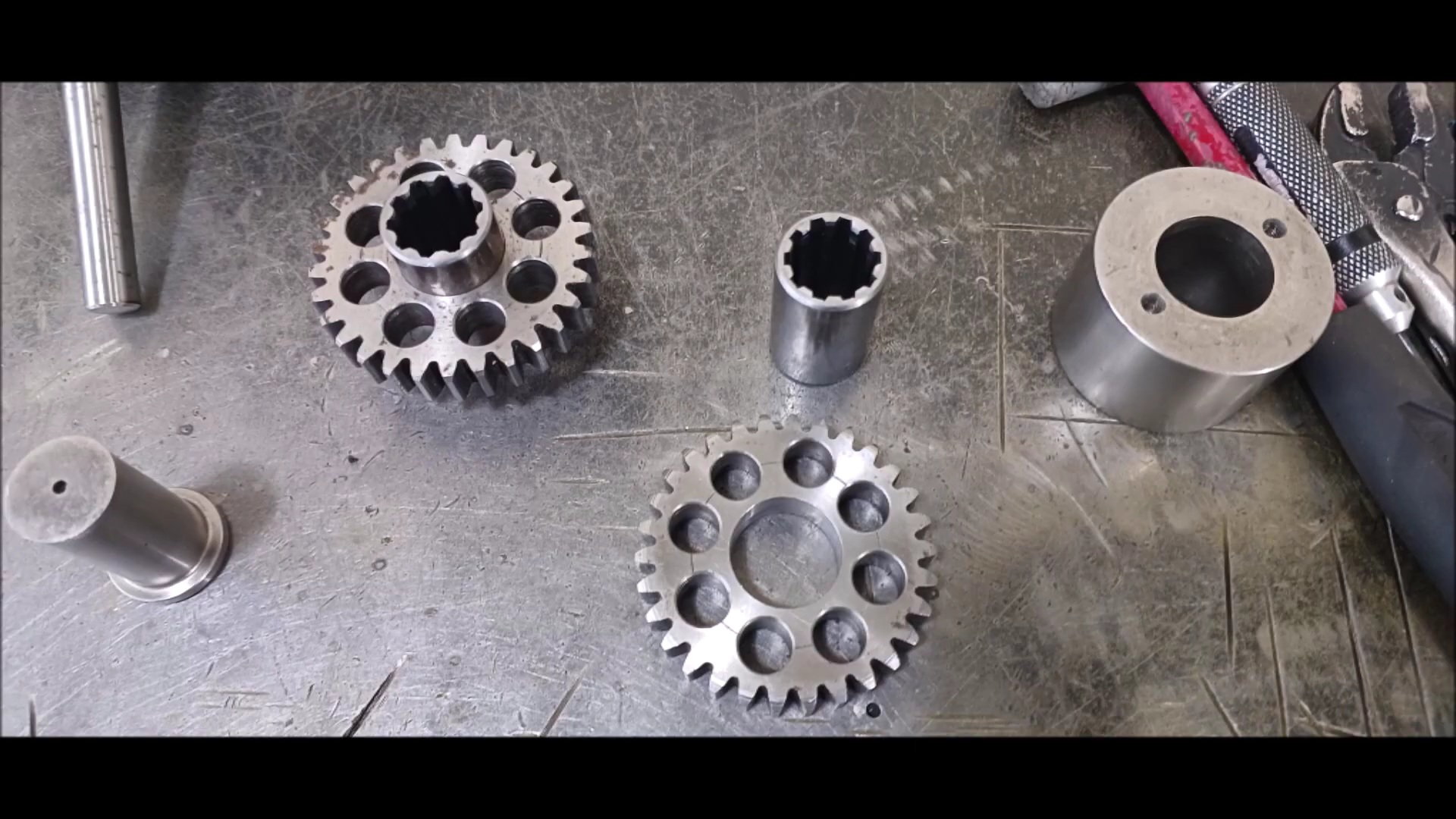
The last gear is a 2.5t module
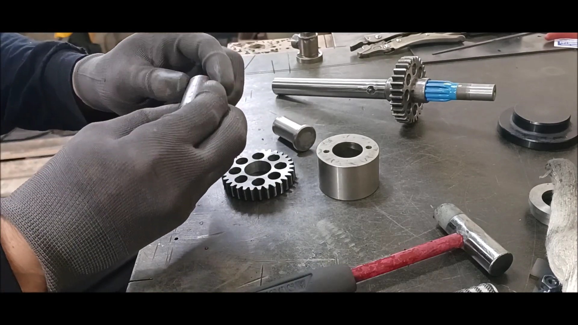
sleeve to gear connection
Depth adjustment - 1
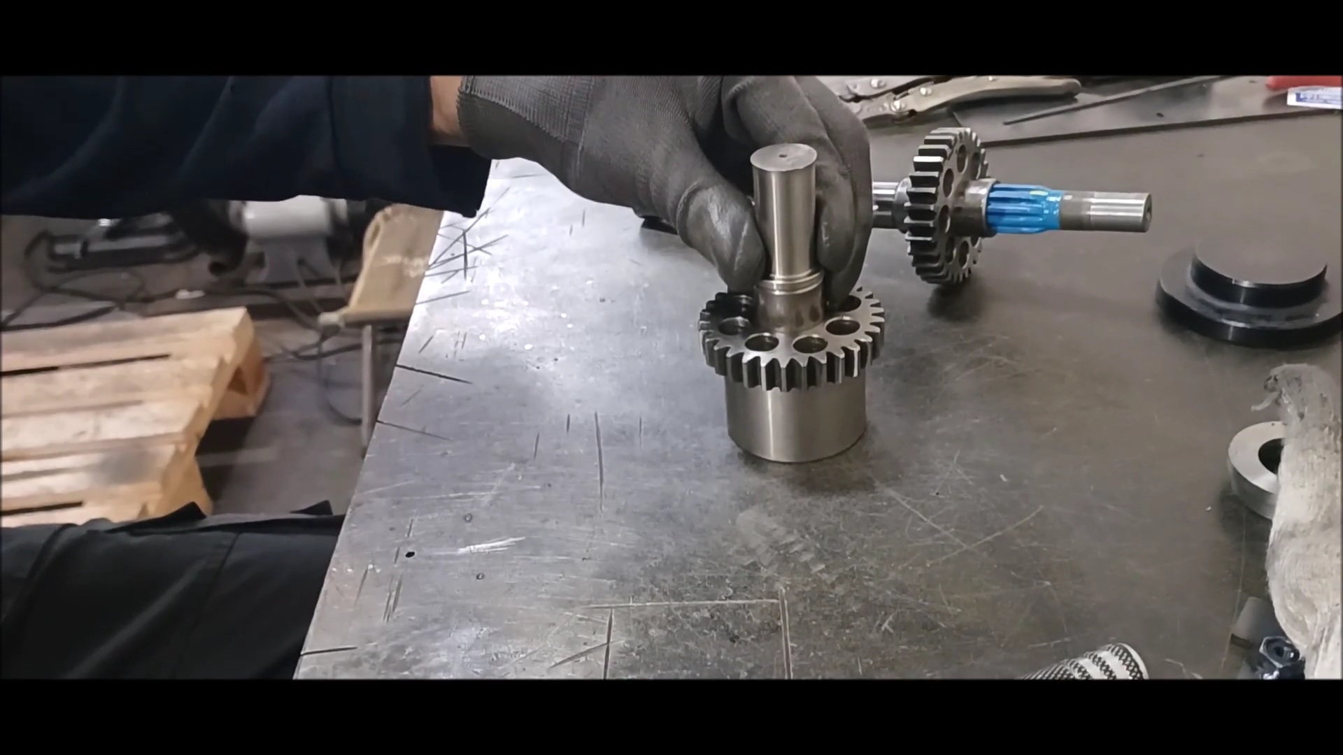
Depth adjustment - 2

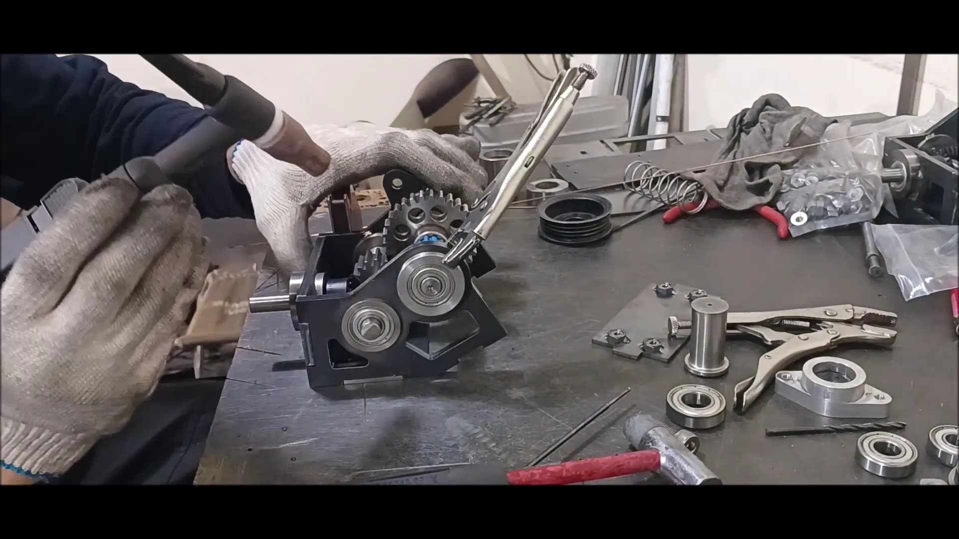
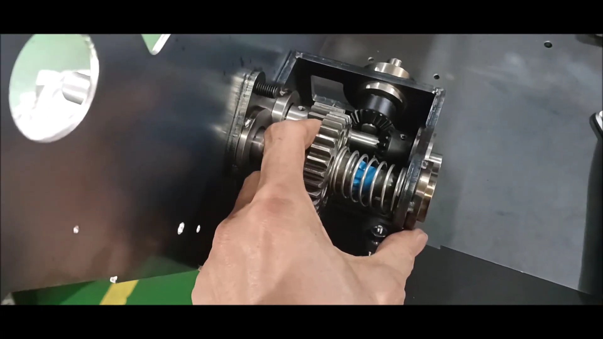
Check the operation of spline
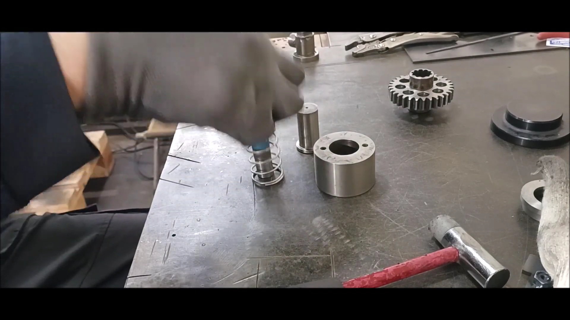
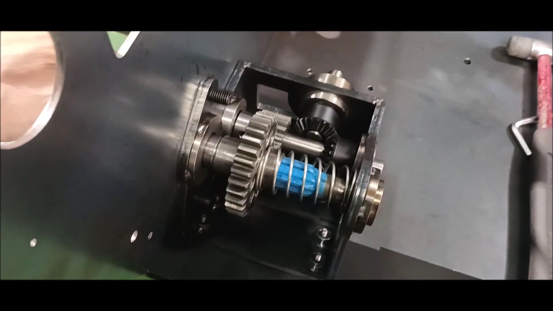
Check spring operation for manual neutral
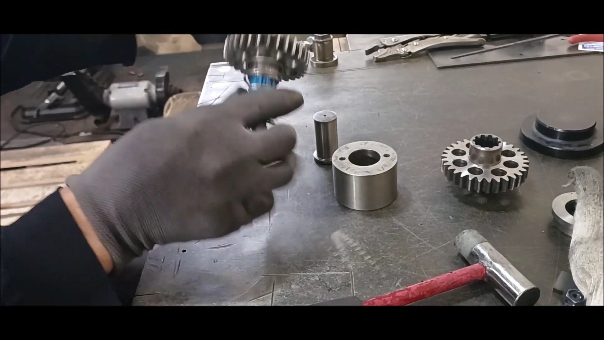
Check the operation of the opposite spline gear
Regards,
Young
Laser-cut gearbox housing
Check the number of bearing boxes and shafts required
Get ready for the round bar
Effective cutting can be done if there is a gap groove on the cutting machine blade
Measure the length of the cut using a steel ruler
round bar cutting
Bearing Housing Shelf Machine Work - 1
Bearing Housing Shelf Machine Work - 2
Bearing Housing Shelf Machine Work - 3
Bearing Housing Shelf Machine Work - 4
Preparation of constant speed joints from vehicle
use a spline
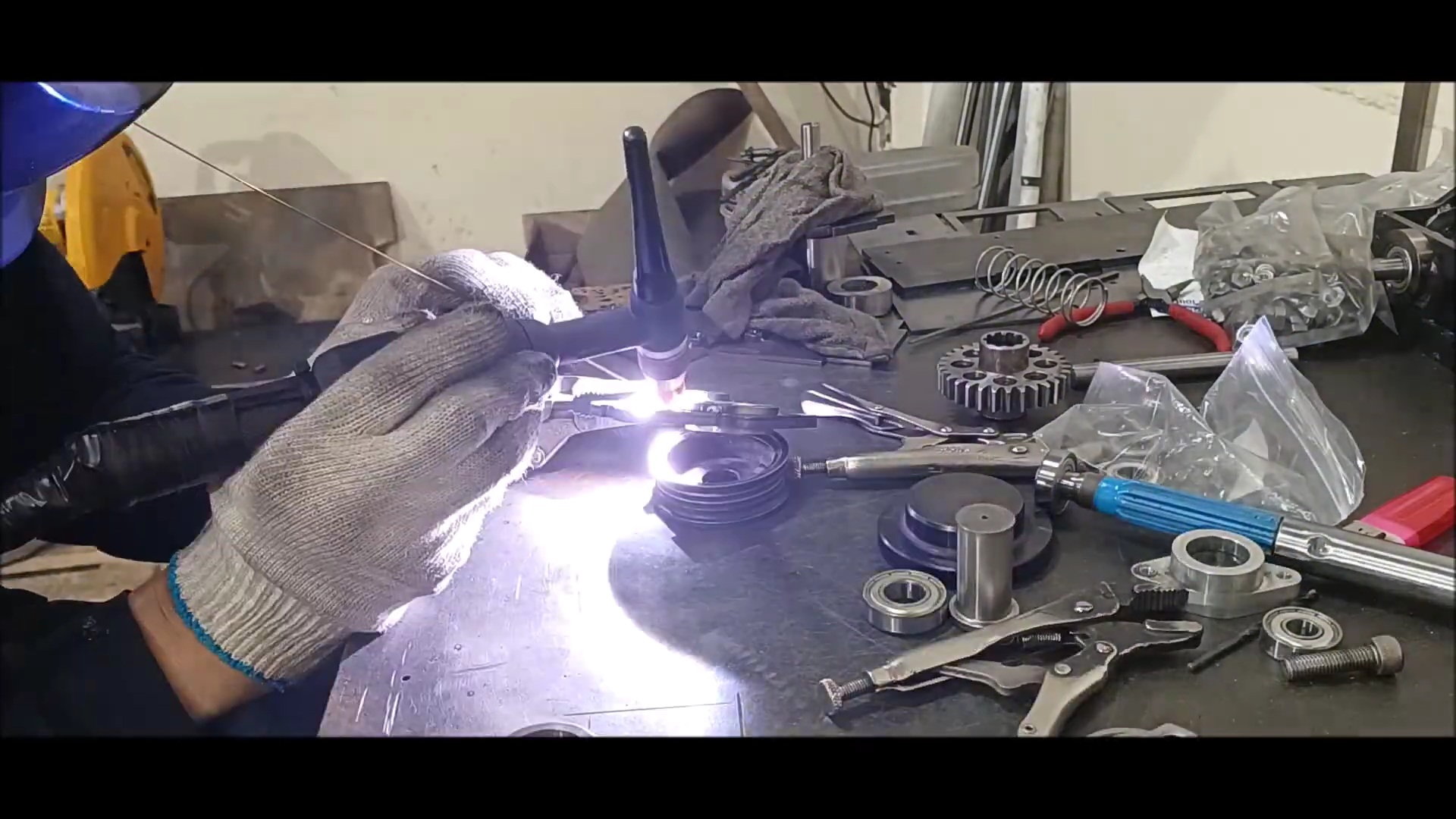
Round bar and welding for cut spline and drive shaft
a welded figure
Thermal deformation occurred while welding the spline coating part, but there is no problem with the operation of the snivel
Manufactured bearing housing
Gearbox assembly
Gearbox assembly
The last gear is a 2.5t module
sleeve to gear connection
Depth adjustment - 1
Depth adjustment - 2
Check the operation of spline
Check spring operation for manual neutral
Check the operation of the opposite spline gear
Last edited by PE YOUNG; 04-23-2023 at 02:03 PM.
04-23-2023, 01:30 PM
#47
Thread Starter
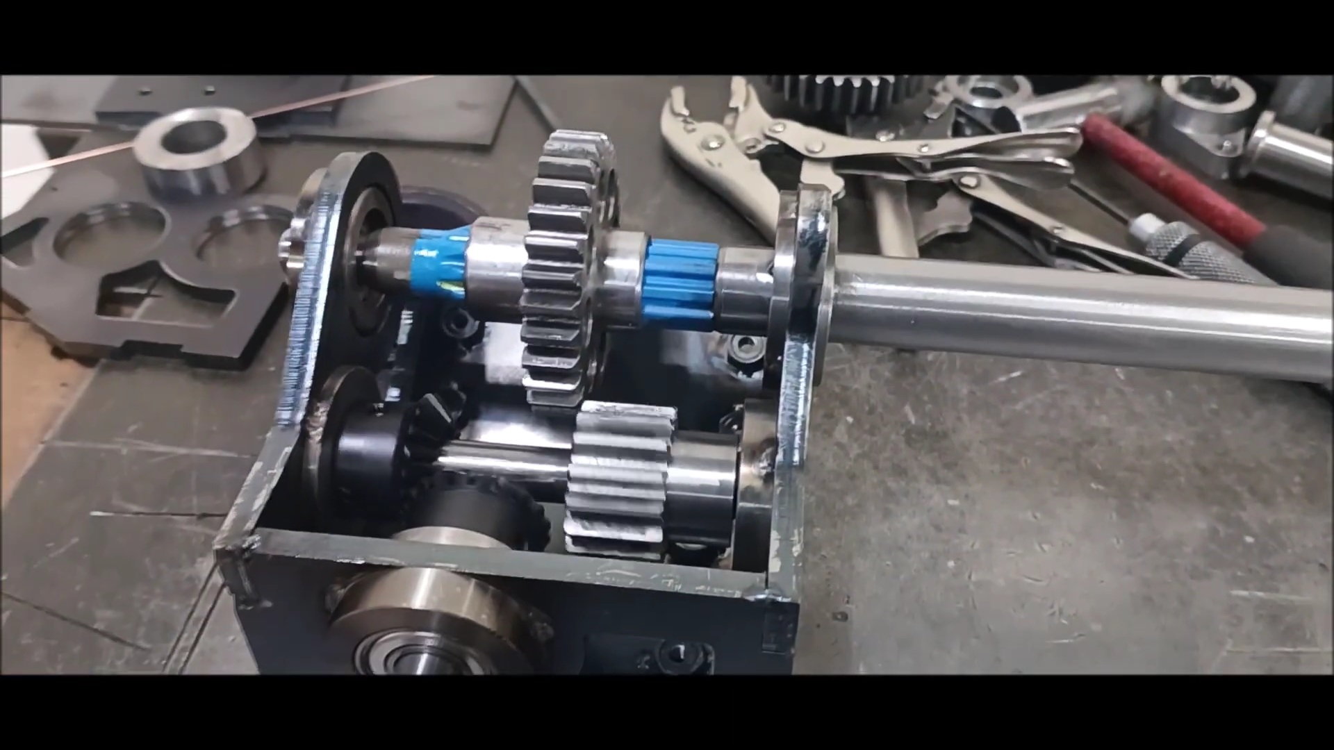
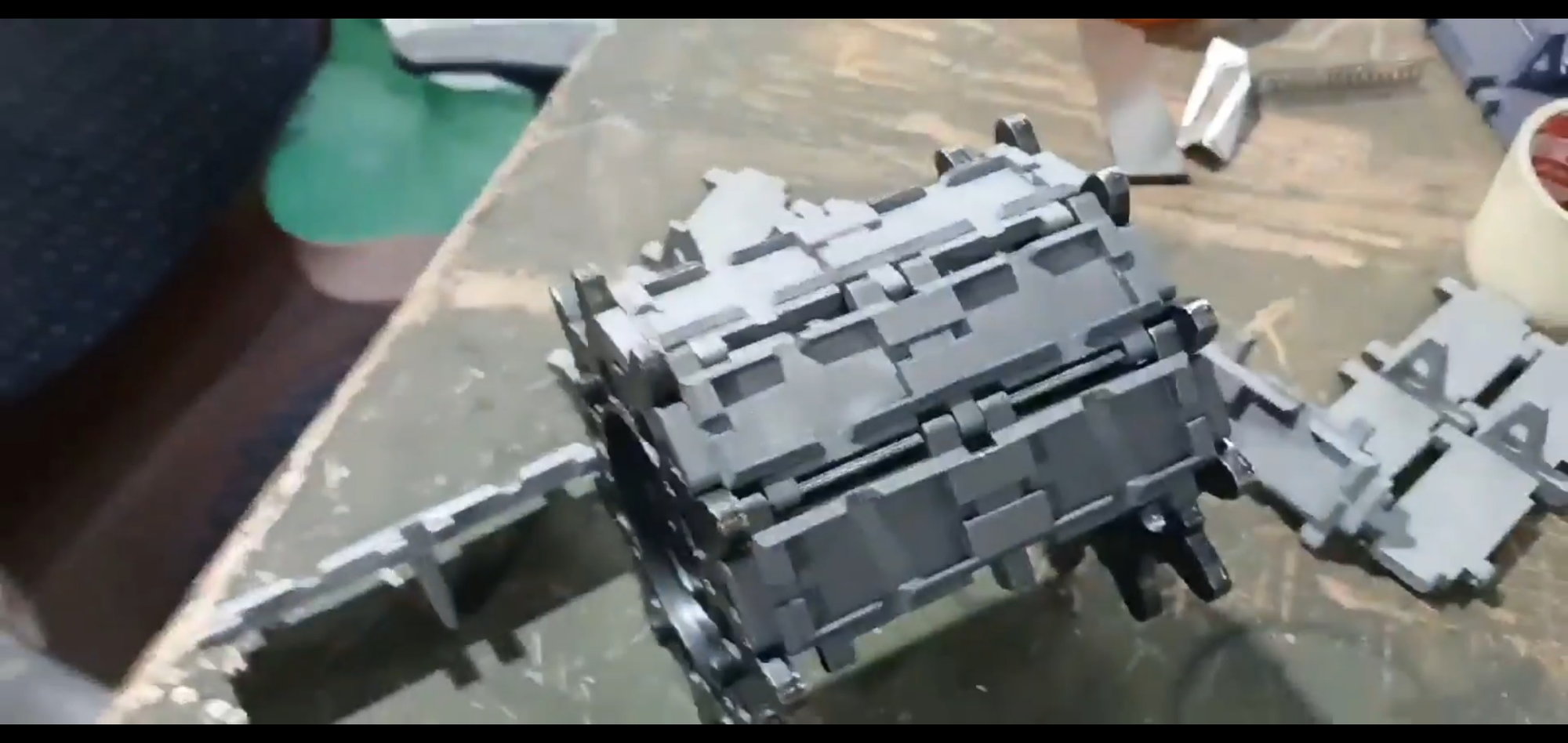
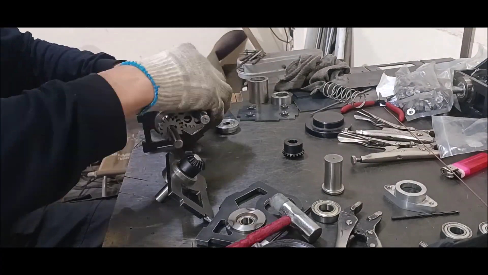
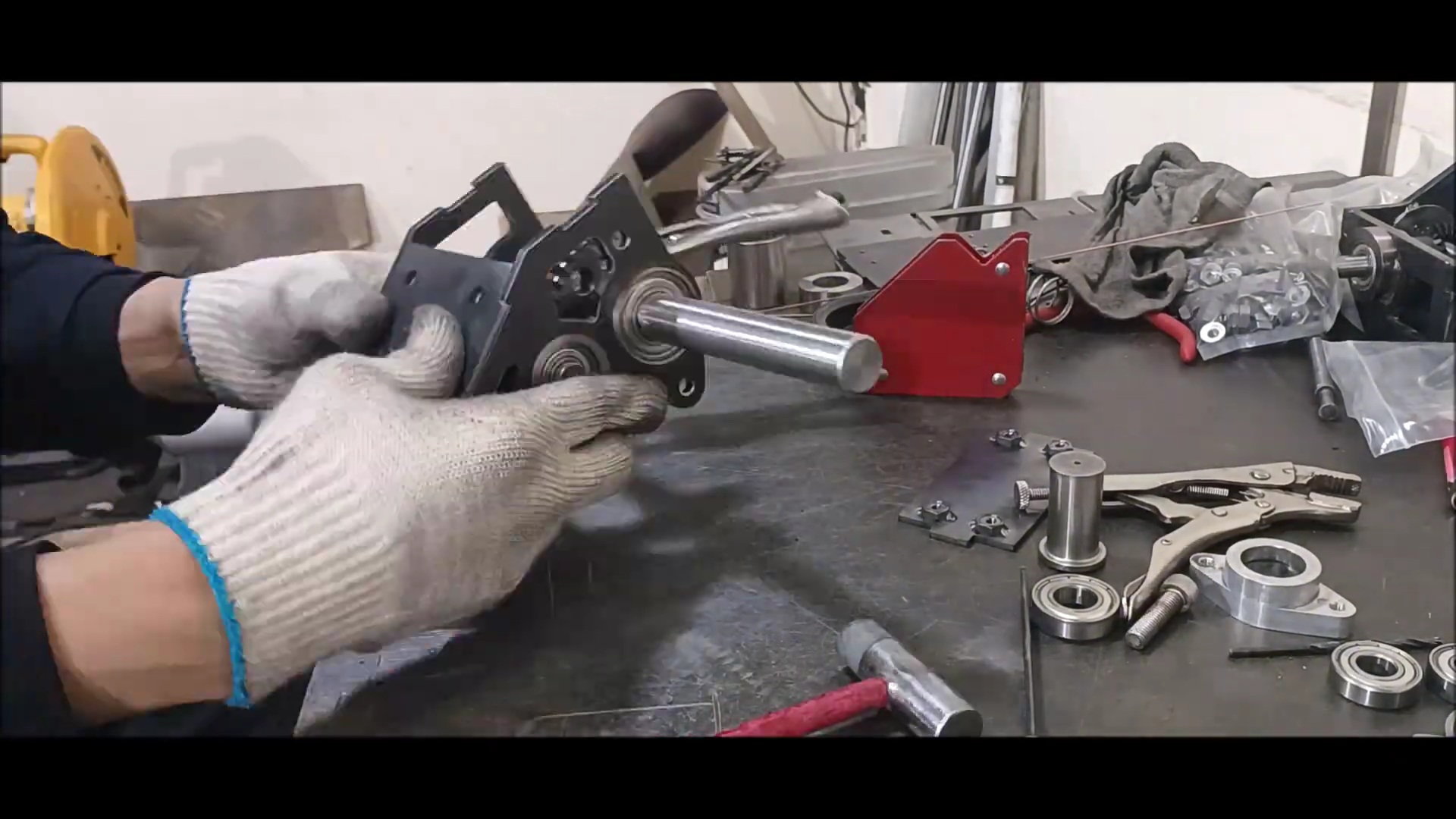
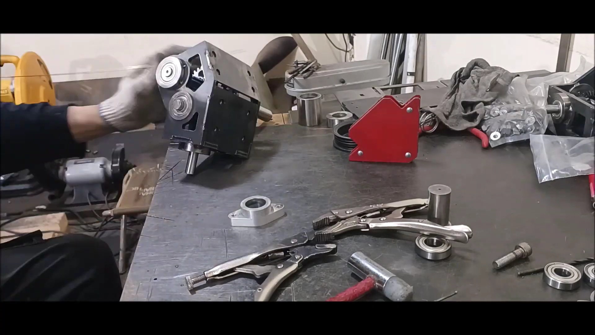
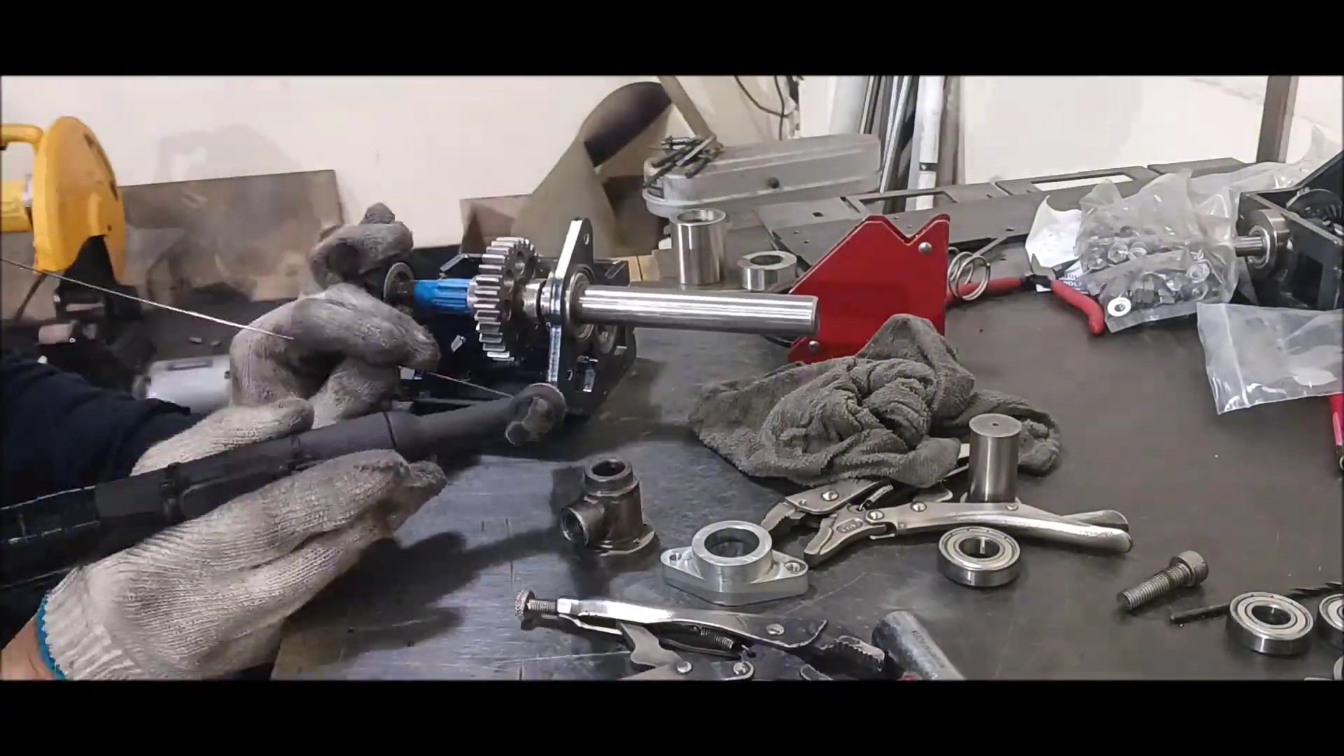
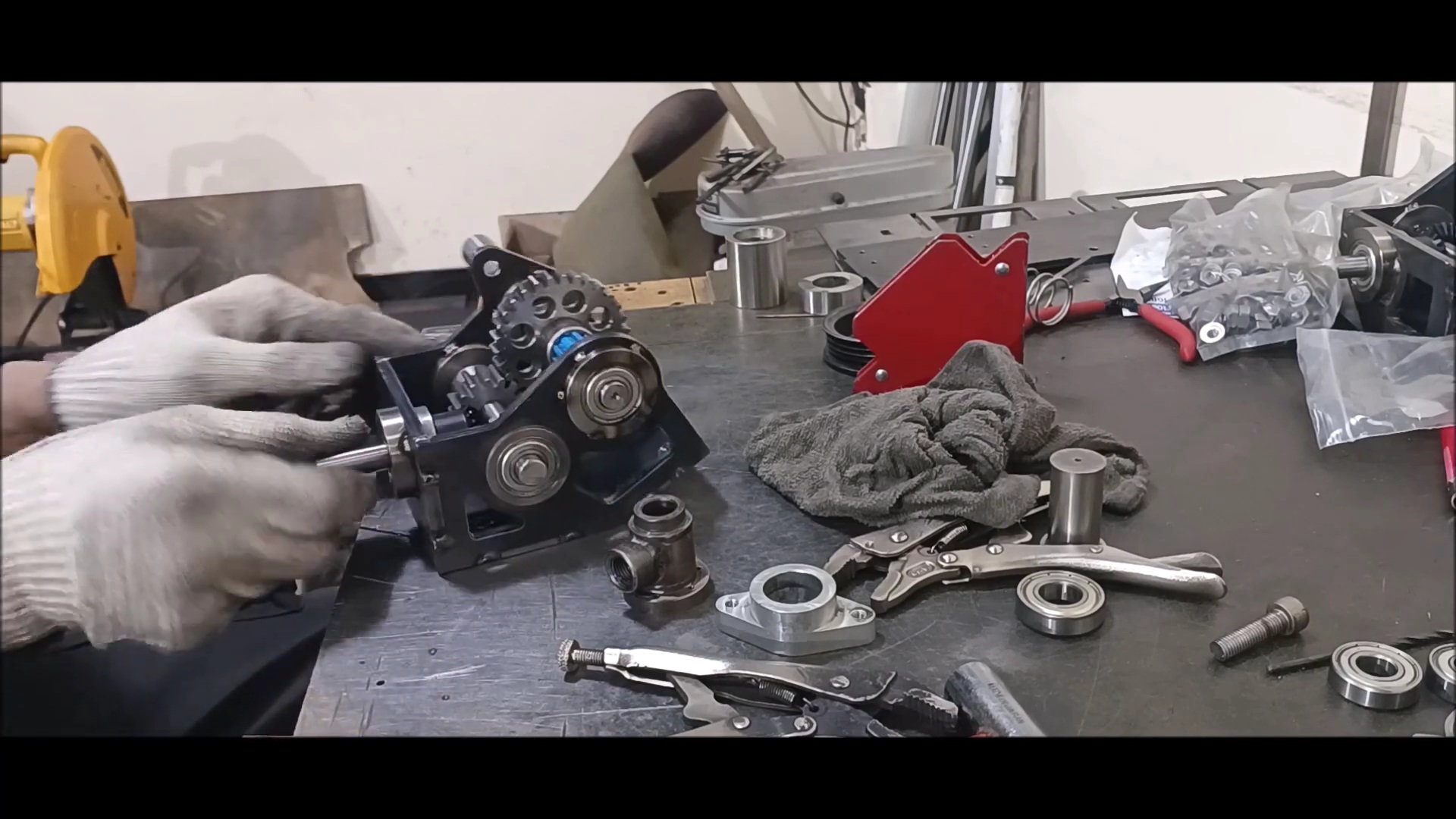
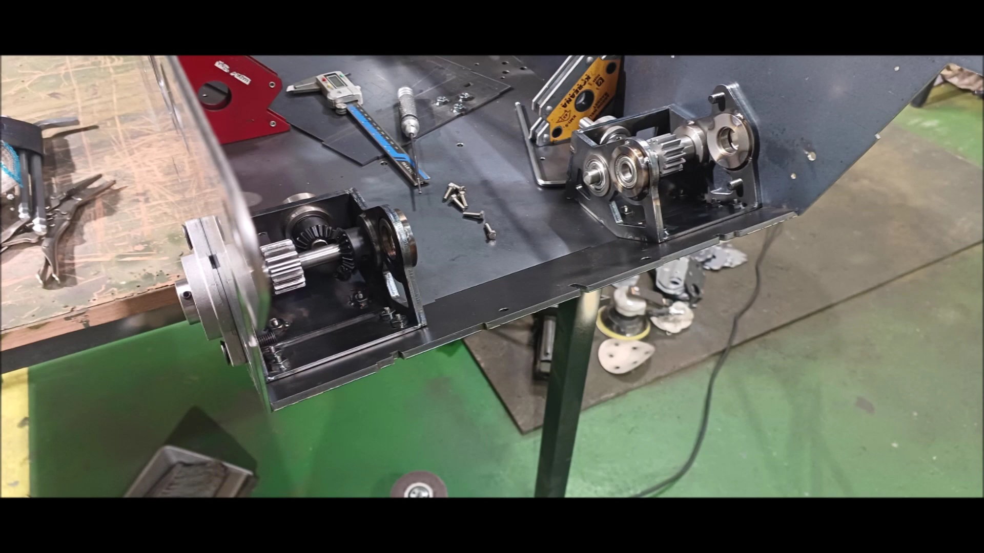
Assembled gearbox shape
Spline gear decoupled
Gearbox Fabrication - 01

Gearbox Fabrication - 02

Gearbox Fabrication - 03

Gearbox Fabrication - 04
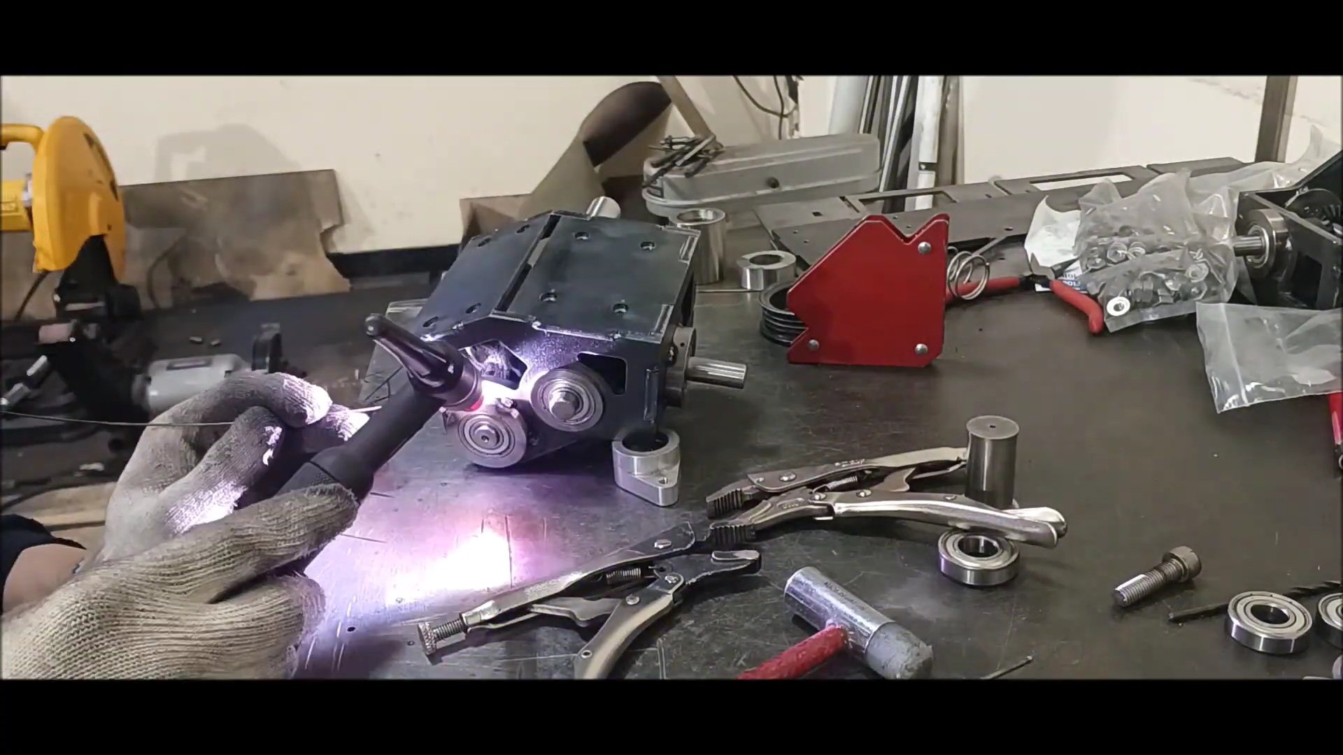
Gearbox Fabrication - 05 [Bearing Insertion with Welded Heat]
Gearbox Fabrication - 06

Gearbox Fabrication - 07

Gearbox Fabrication - 08

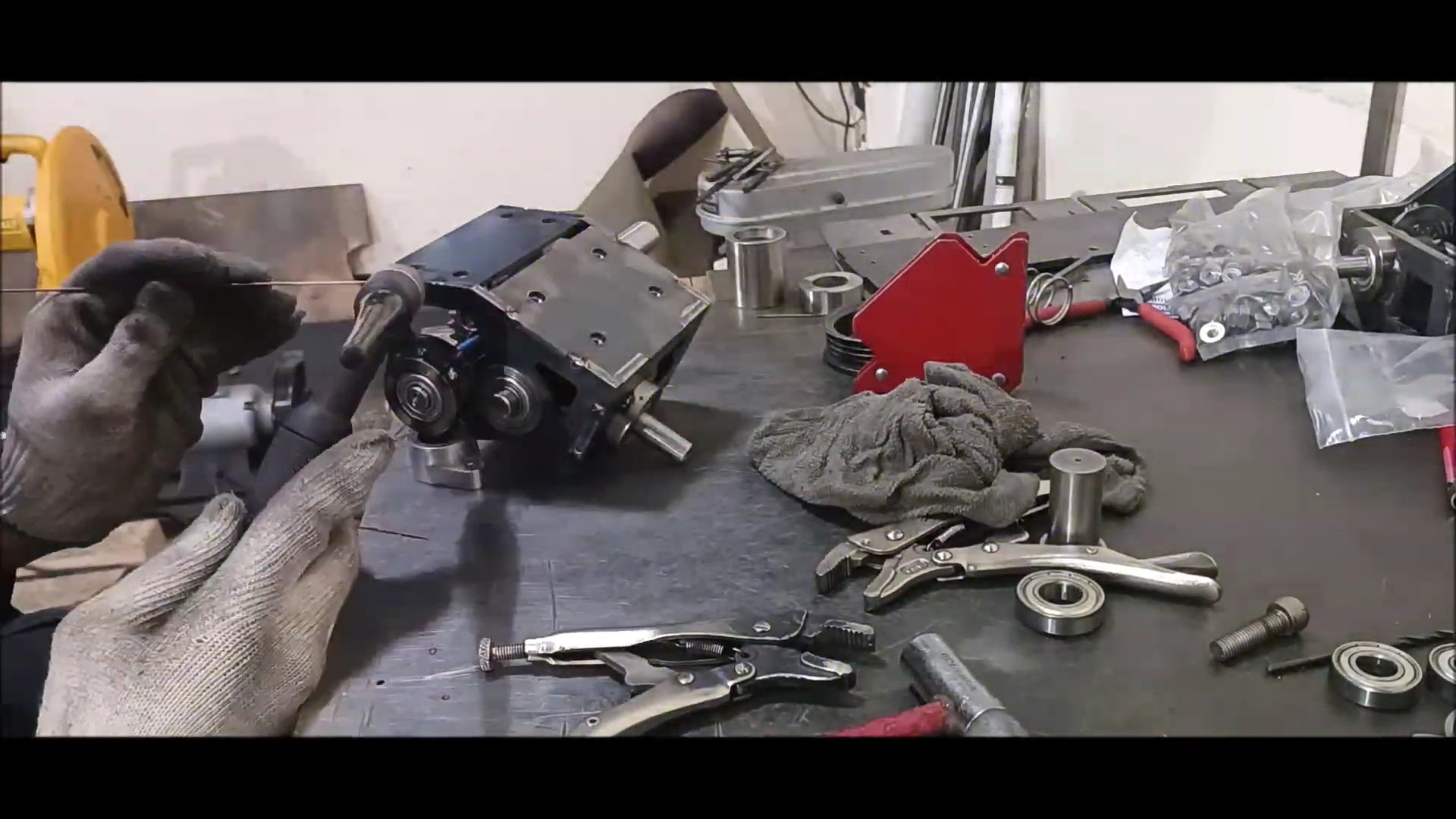
Gearbox Fabrication - 09
Gearbox Fabrication - 10
Gearbox Fabrication - 11

Gearbox Fabrication - 12
Gearbox Fabrication - 13
Gearbox Fabrication - 14

Gearbox Fabrication - 15

Gearbox Fabrication - 16
Gearbox Fabrication - 17
Gearbox Fabrication - 18

Gearbox Fabrication - 19
Gearbox Fabrication - 20

Gearbox Fabrication - 21
Gearbox Fabrication - 22

Gearbox Fabrication - 23
04-23-2023, 01:52 PM
#48
Thread Starter
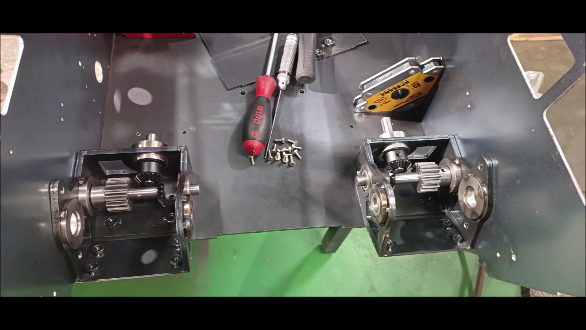
Gearbox Fabrication - 24
Gearbox Fabrication - 25

rbox Fabrication - 26

left and right complete gearbox

left and right complete gearbox [The neutral spring is out]

Positioned on the rear of the body

Positioned on the rear of the body

Prepare to secure to the side of the body

Fix it in an irin fashion
Go to the left and right side plates
Secure the bolt by positioning it
Fix the rear lower plate

Fix the rear lower plate

Fix the rear lower plate

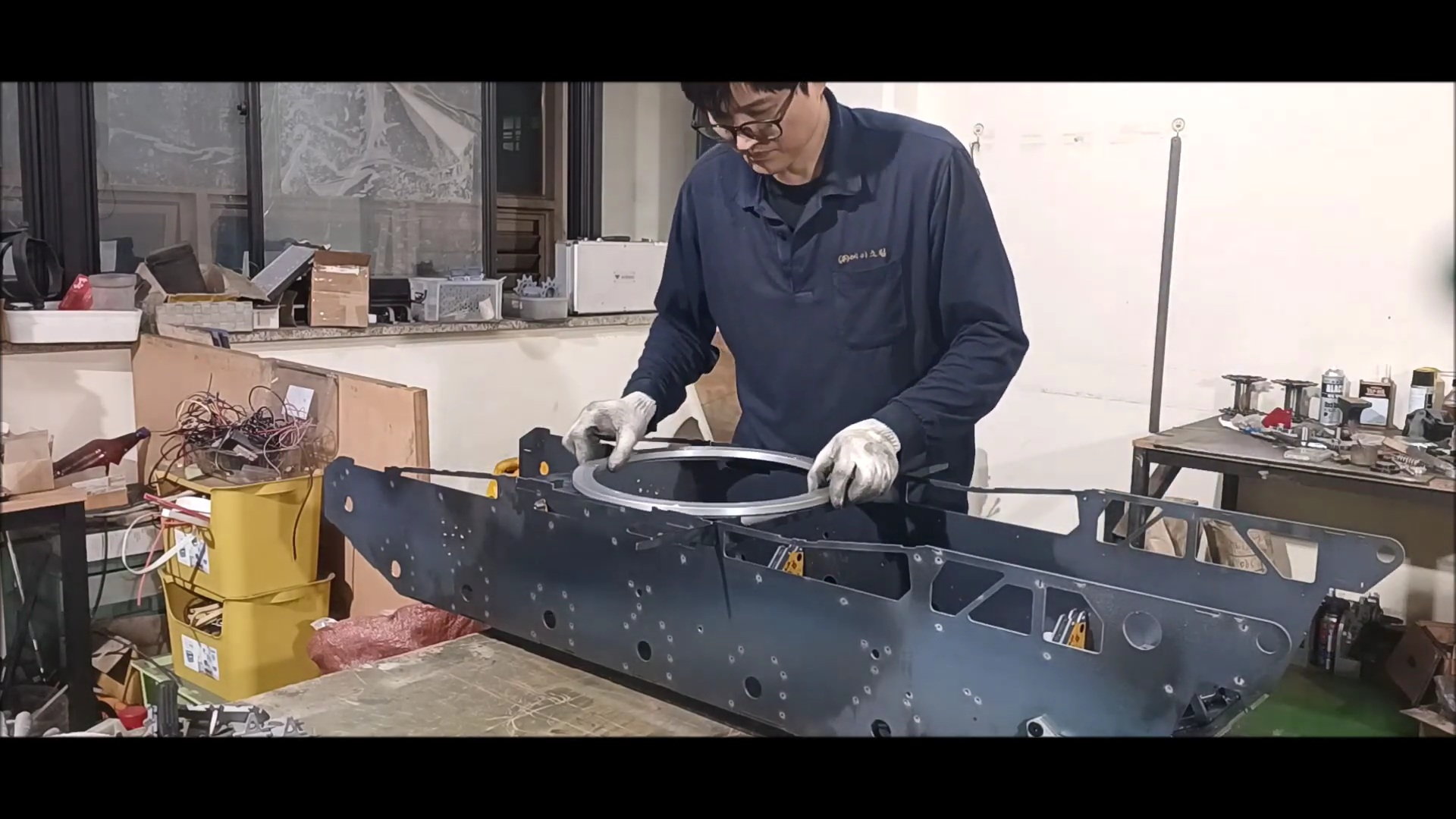
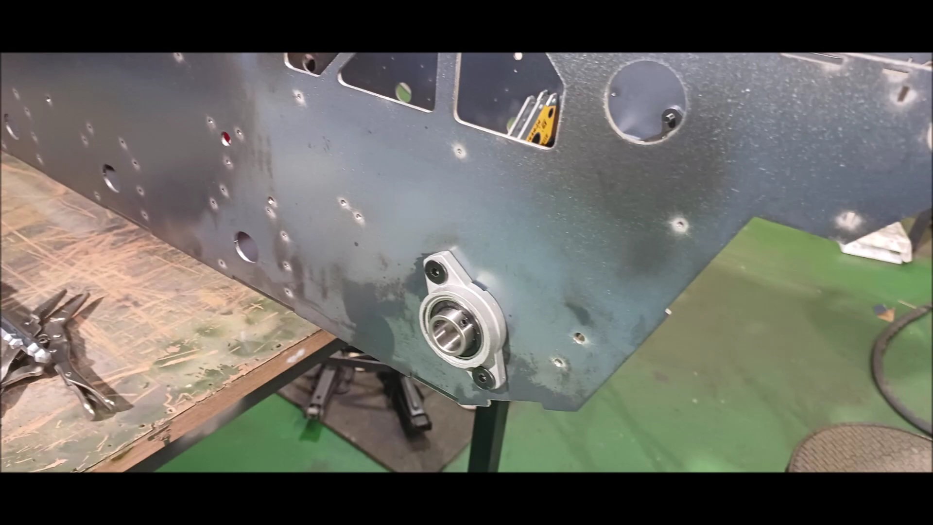
Setting the turret bearing position
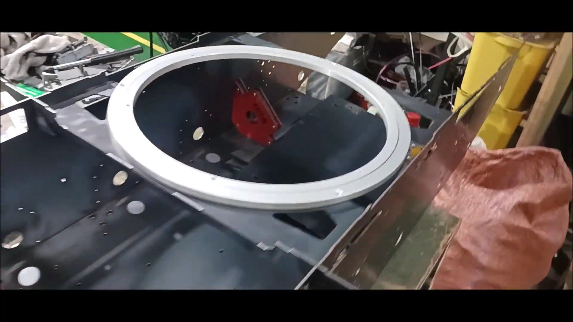
Setting the turret bearing position
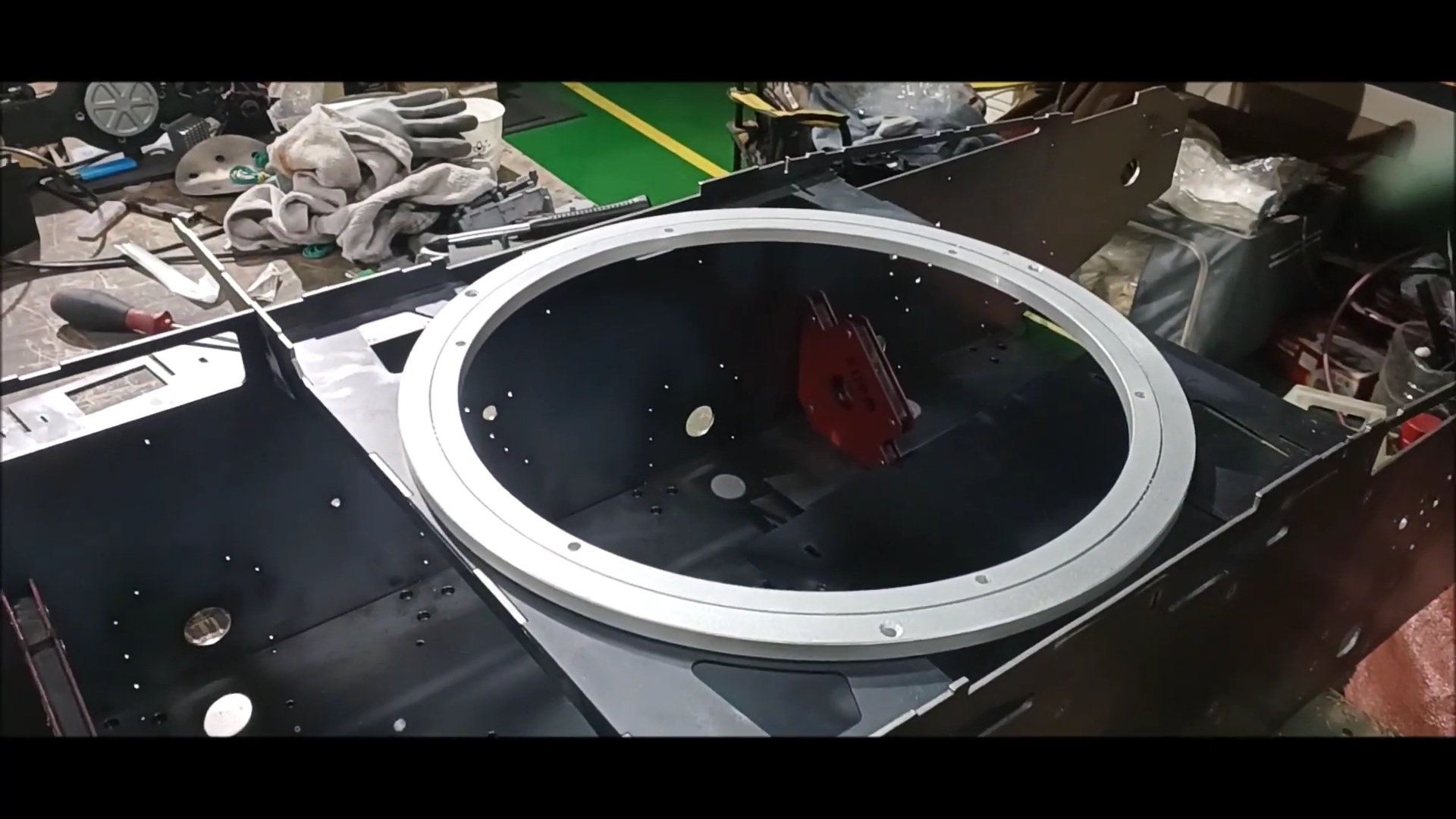
Setting the turret bearing position
Gearbox complete
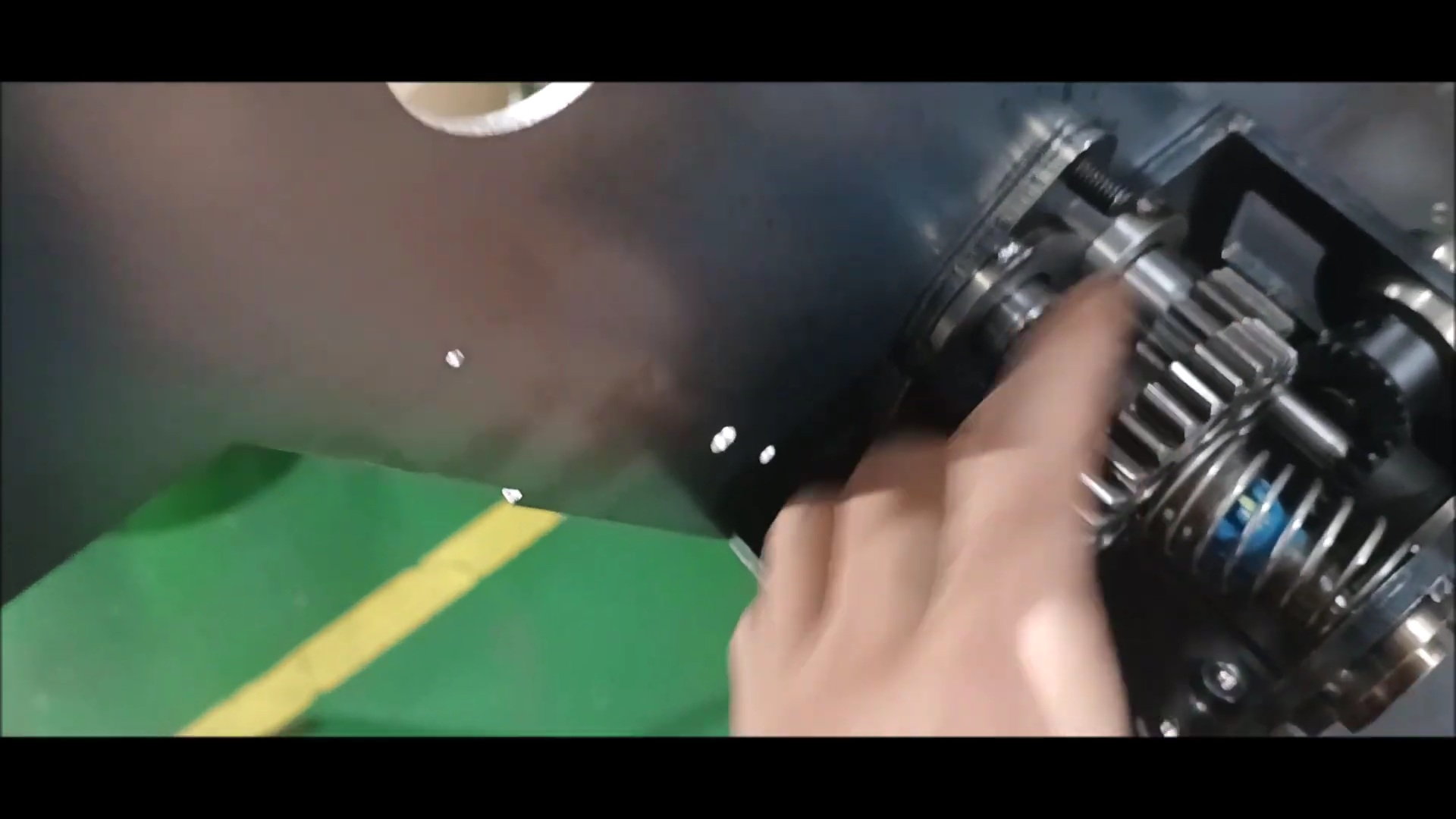
Manual Neutral Test

Manual Neutral Test
Manual Neutral Test

Manual Neutral Test

Manual Neutral Test
In the next episode, body welding will proceed