


Ziroli 1/6 Hellcat Build
 04-15-2018, 10:39 AM
#201

Thread Starter
Looking at the Actuonix T-16 models, maybe there would be a way to secure the servo to the front edge of the sliding canopy, above the rails I installed? But the servo arms would be visible, not hidden like the P-47 example I found. The slider from Dynamic Balsa is an H- shape - if I take the outer leg of the H off, I may be able to have it slide under the fuse sheeting, say, a 4" length extending forward of the sliding canopy, forward of the dashboard, that the hidden servo would then to?
Already starting to think about dropping features in order to get the plane flying by summer/fall. Will need to decide quickly, with a solid solution, or keep moving without them.
On my Byron version, I had tried rare earth magnets to keep the canopy closed. After several flights, ended up using a screw on either side to secure it. I could take the screws out, opening the cockpit for static display. Wasn't a museum piece, but worked and still won a crowd vote award at an ad-hoc event (the museum birds weren't there that day!).
 04-25-2018, 06:38 PM
#202
Thread Starter
Fuse sheeting under stab installed, both sides. First attempt at fitting the sheet under the curve of the stab and fitting the control tubes for elevator and rudder ended in scrap. However, the scrap piece was useful as a template to create the next pieces, that fit well.
Next steps will include installing the fin, installing/shaping the tail piece under the rudder, installing throttle, choke, air valve servos and air valve.
Starting to check into radios. I have a Futaba 9C with a 2.4 Ghz module - and have realized that the radio itself must be about 20 years old and that the FASST receivers I've been using are no longer available. Geez, time flies. Radio has been cared for, but what am I risking with a radio this old? And, technology has certainly changed. So, looking at the Futaba 14SGA - price looks acceptable, will run my FASST receivers and the new FASSTest receivers, plus telemetry. Good enough, I expect.
05-11-2018, 05:57 PM
#203
Thread Starter
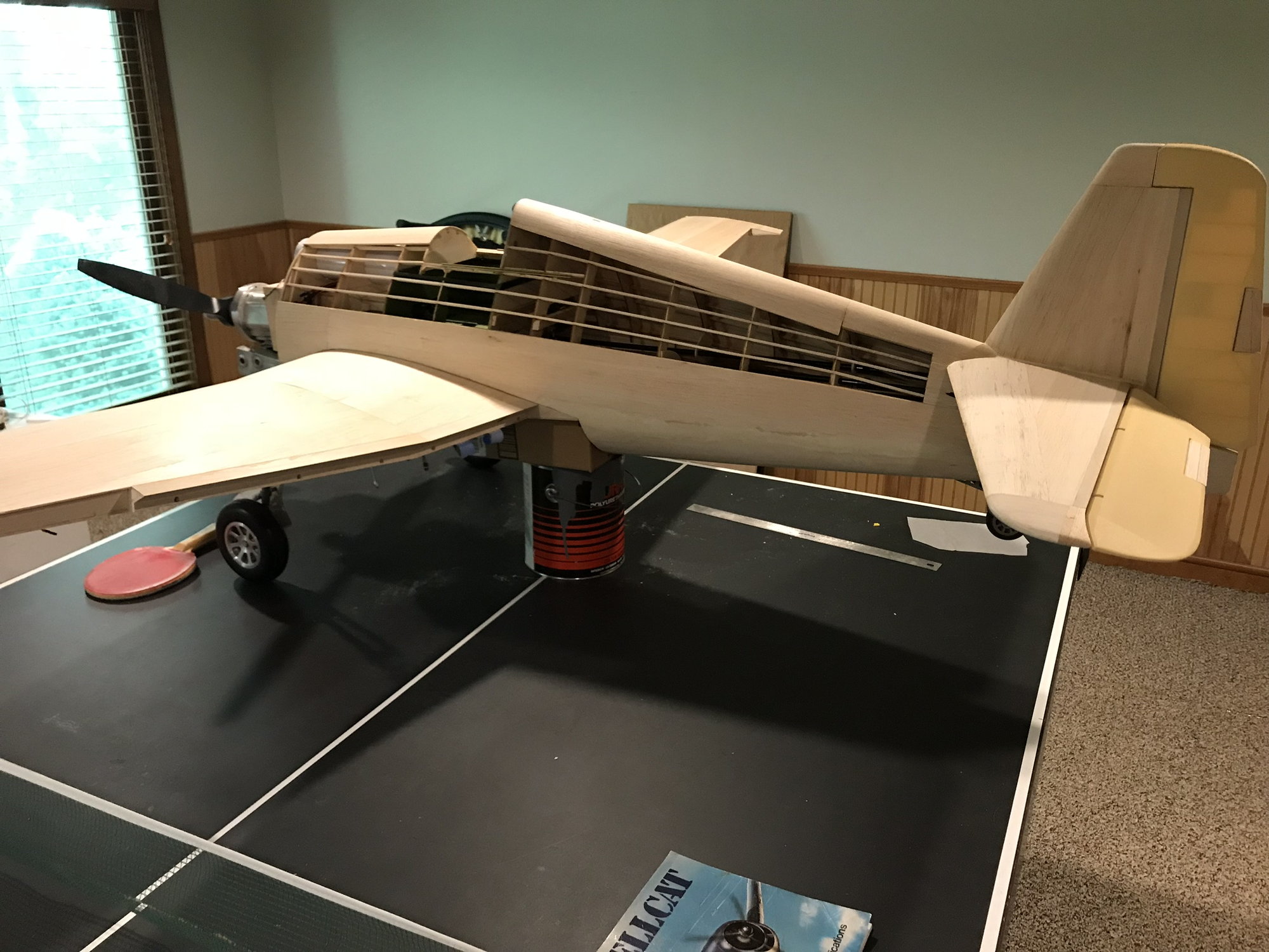
Vertical fin installed.
Had a bit of a set back. Humidity change in Michigan, from Winter to Spring is not insignificant, and the horizontal stab was no longer parallel with the wing. Had a choice to make -
So, I went with 1 and so far, so good. Waited a week after performing corrective actions and stab is still parallel to wing. Calling it good enough. Lesson learned for next build.

Had a bit of a set back. Humidity change in Michigan, from Winter to Spring is not insignificant, and the horizontal stab was no longer parallel with the wing. Had a choice to make -
- tear the stab off and re-level it, perhaps even go farther in rebuild, or,
- leave everything as is and try to untwist it
So, I went with 1 and so far, so good. Waited a week after performing corrective actions and stab is still parallel to wing. Calling it good enough. Lesson learned for next build.
05-25-2018, 06:51 PM
#204
Thread Starter
Tail Cone installed, sanded to shape. Hollowed it out a bit and cut holes for future - in case I go forward with light set, will have means to pass taillight wire through. Also, decided to use pegs for additional strength. They are long enough to engage the last ply former.

Outline cut, disc sanded
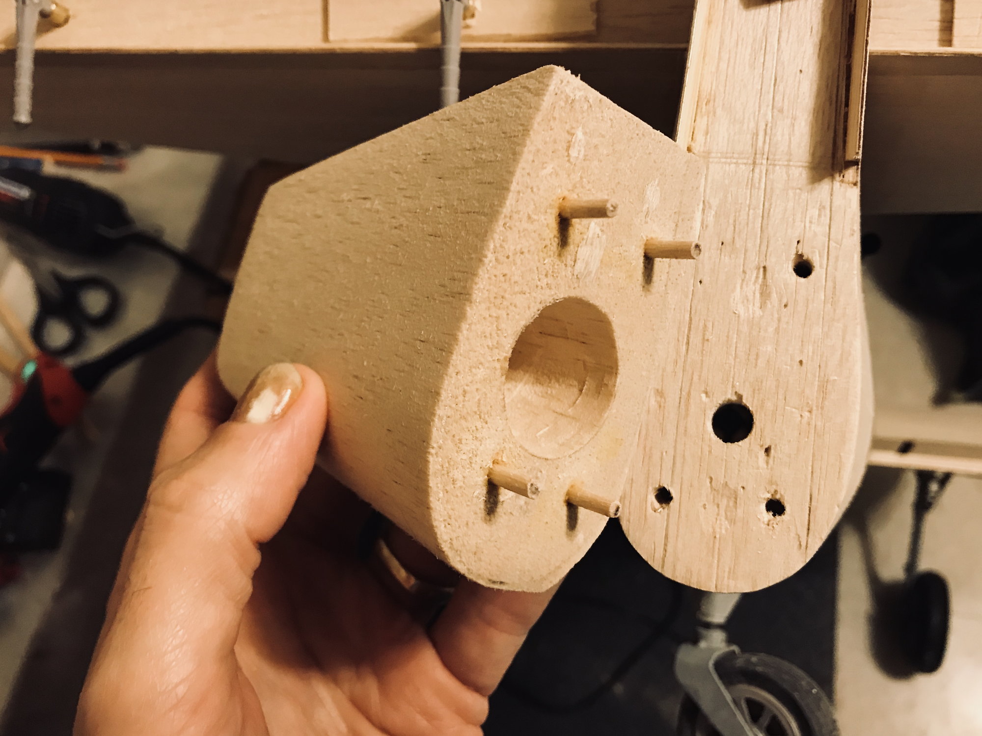
Pegs, hollowed out
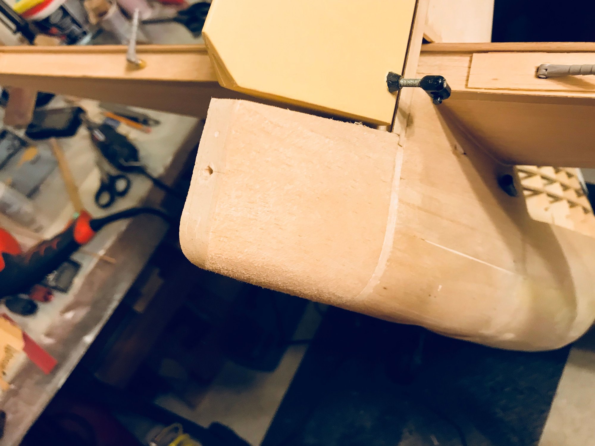
Sanded to fuse shape
Outline cut, disc sanded
Pegs, hollowed out
Sanded to fuse shape
06-09-2018, 05:43 PM
#205
Thread Starter
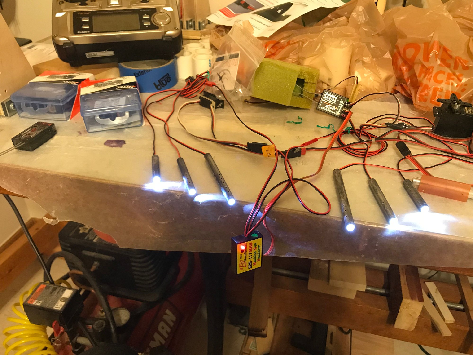
Gun barrels from IFlyTailies arrived. Had them modified to fit 5mm high intensity LEDs. Gun light sequencer from ElectroDyanics (EDR-117MGS Machine Gun System)
Working now on throttle and choke servo location/installation.
Working now on throttle and choke servo location/installation.
Last edited by DaleCS; 06-09-2018 at 07:33 PM.
06-23-2018, 07:23 PM
#206
Thread Starter
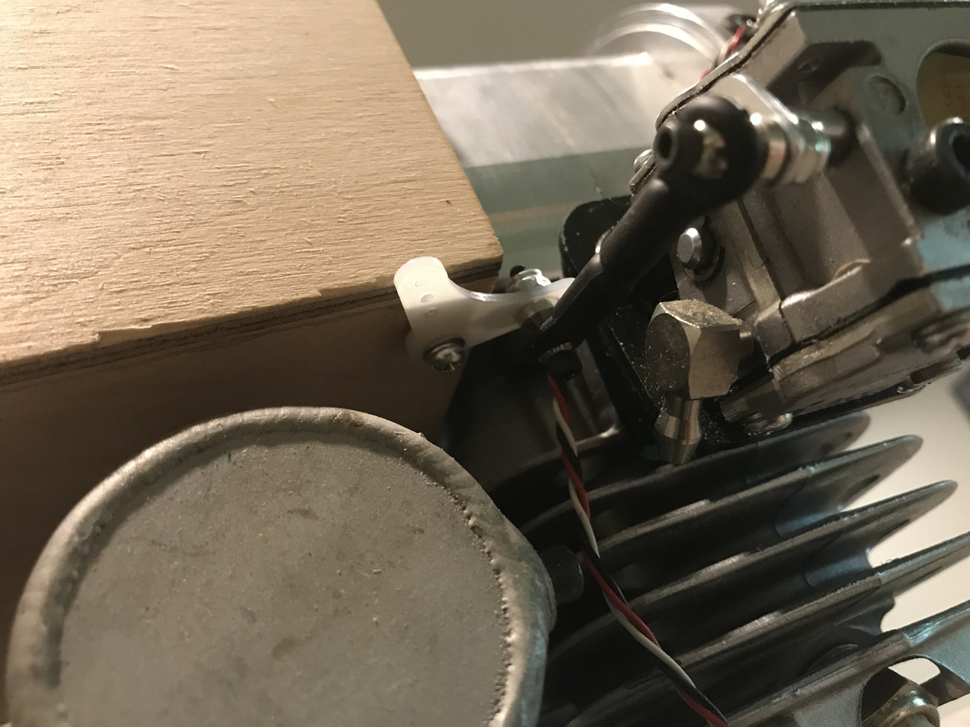
Choke linkage installed. .
Original carb had a choke lever that could be reached through the front of the cowling. Original carb is no longer made - the Walbro replacement has the choke lever on the back of the carb - can't get to it through the cowling front. I didn't want to put a manual link through the cowling side. Therefore, went with a choke servo and bell crank setup. Went with the same high torque servo used elsewhere on the plane, as I'm leaving the spring/ball in place. Tried removing it, but without the ball held into the choke lever's detent, there was quite a bit of play - didn't like the idea of what vibration might do (wear, metal particles entering carb).
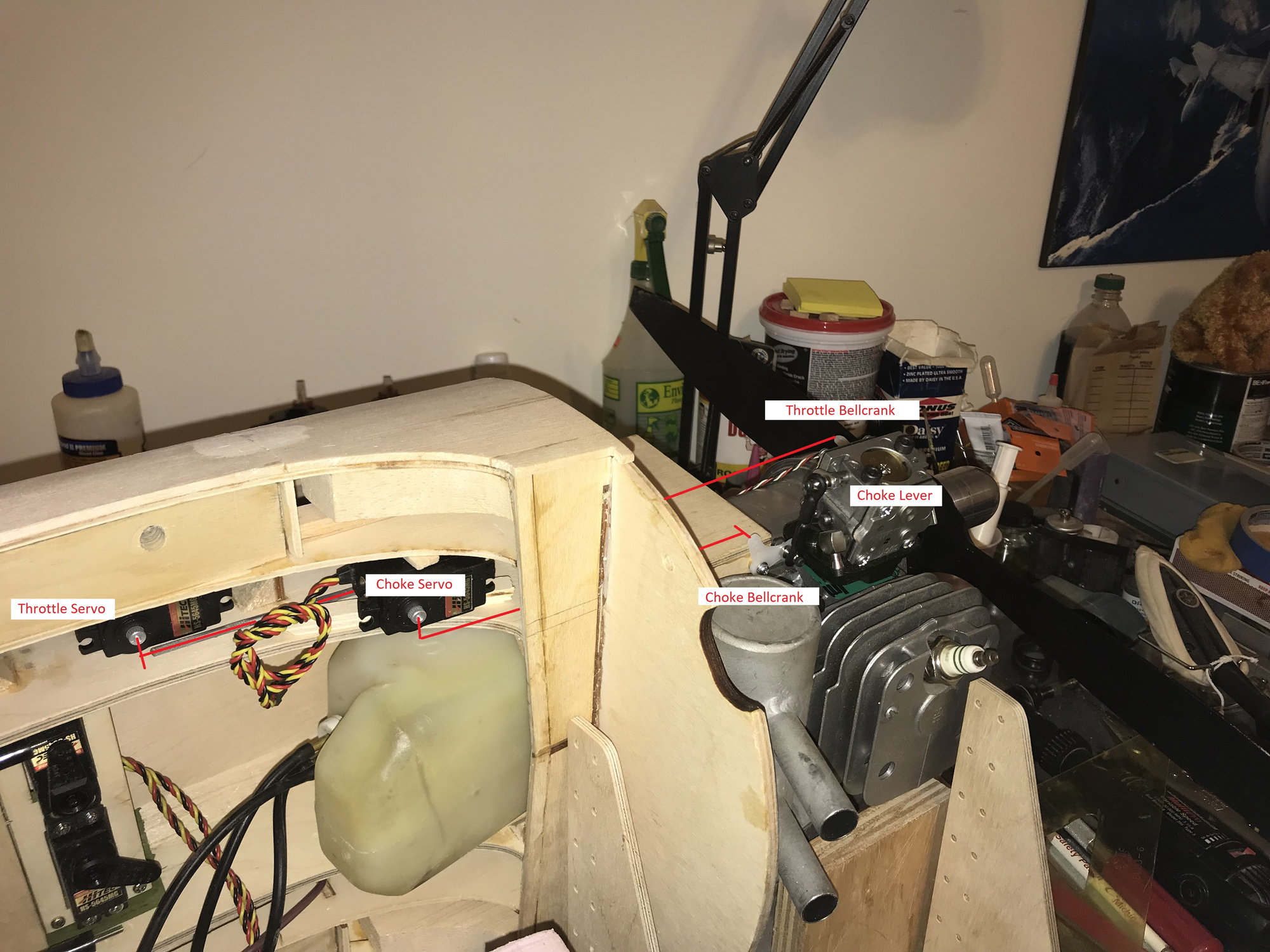
3rd picture shows where I expect to put the throttle and choke servos. The choke servo and fuel tank will extend below the fuselage, into the top of the wing - so the W-1 ribs will need to be notched.

Original carb had a choke lever that could be reached through the front of the cowling. Original carb is no longer made - the Walbro replacement has the choke lever on the back of the carb - can't get to it through the cowling front. I didn't want to put a manual link through the cowling side. Therefore, went with a choke servo and bell crank setup. Went with the same high torque servo used elsewhere on the plane, as I'm leaving the spring/ball in place. Tried removing it, but without the ball held into the choke lever's detent, there was quite a bit of play - didn't like the idea of what vibration might do (wear, metal particles entering carb).
3rd picture shows where I expect to put the throttle and choke servos. The choke servo and fuel tank will extend below the fuselage, into the top of the wing - so the W-1 ribs will need to be notched.
 07-04-2018, 10:24 AM
#208
Thread Starter
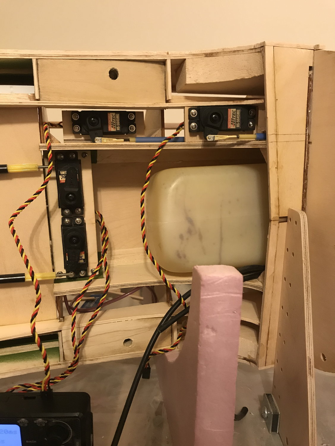
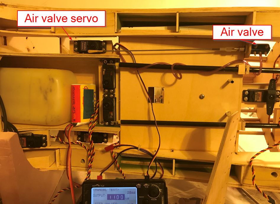
Retract air valve and its servo installed. Chose the 'back of cockpit' location for the valve, for ease of installation and access for maintenance/air line replacement, if ever necessary. On the 1/5 scale, I could have mounted it forward. On the 1/6 scale, I probably could have gotten it in, forward, but it would have been very difficult to remove, install airlines or remove/reinstall the valve.
07-30-2018, 04:15 PM
#209
Thread Starter
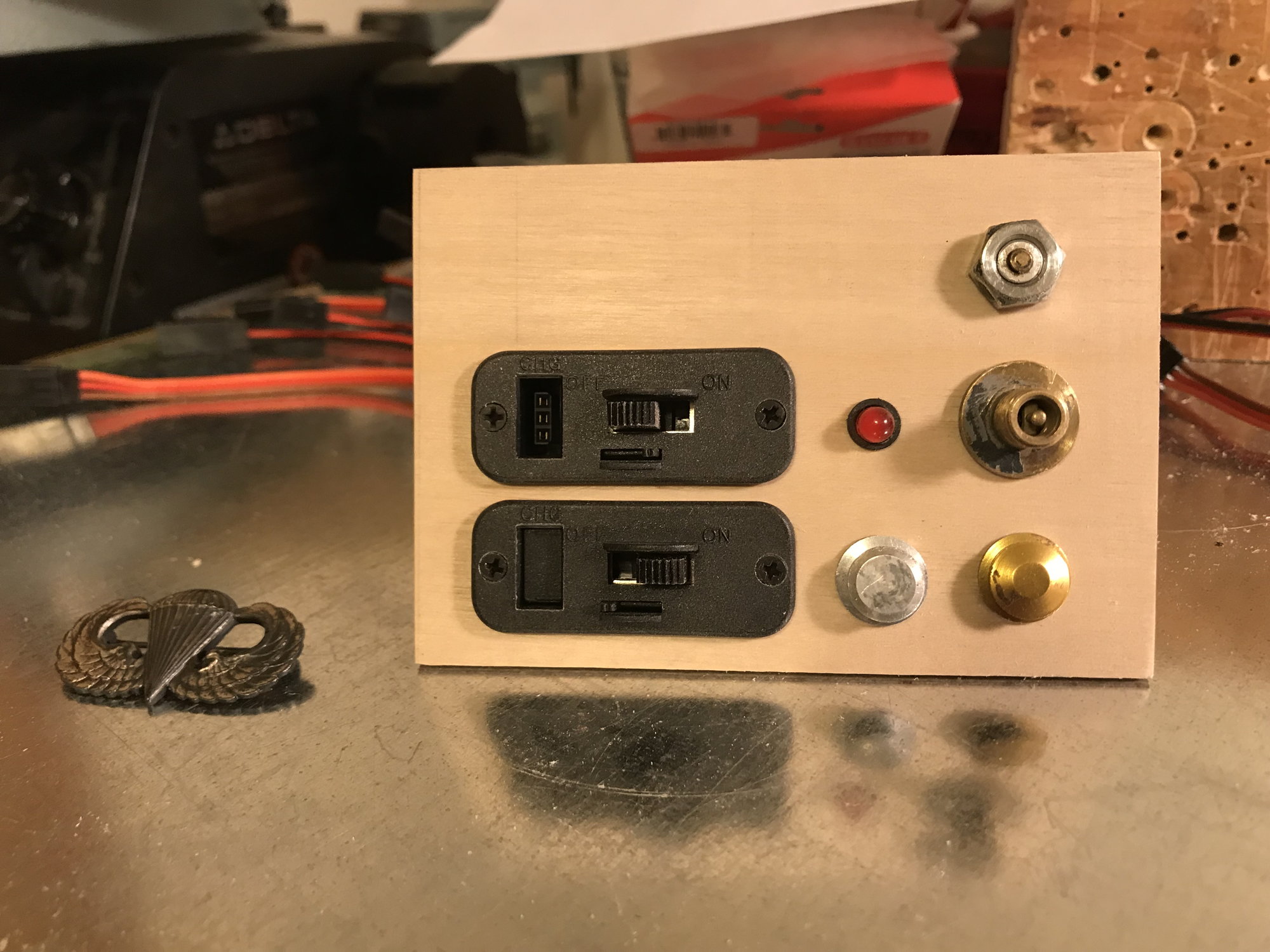
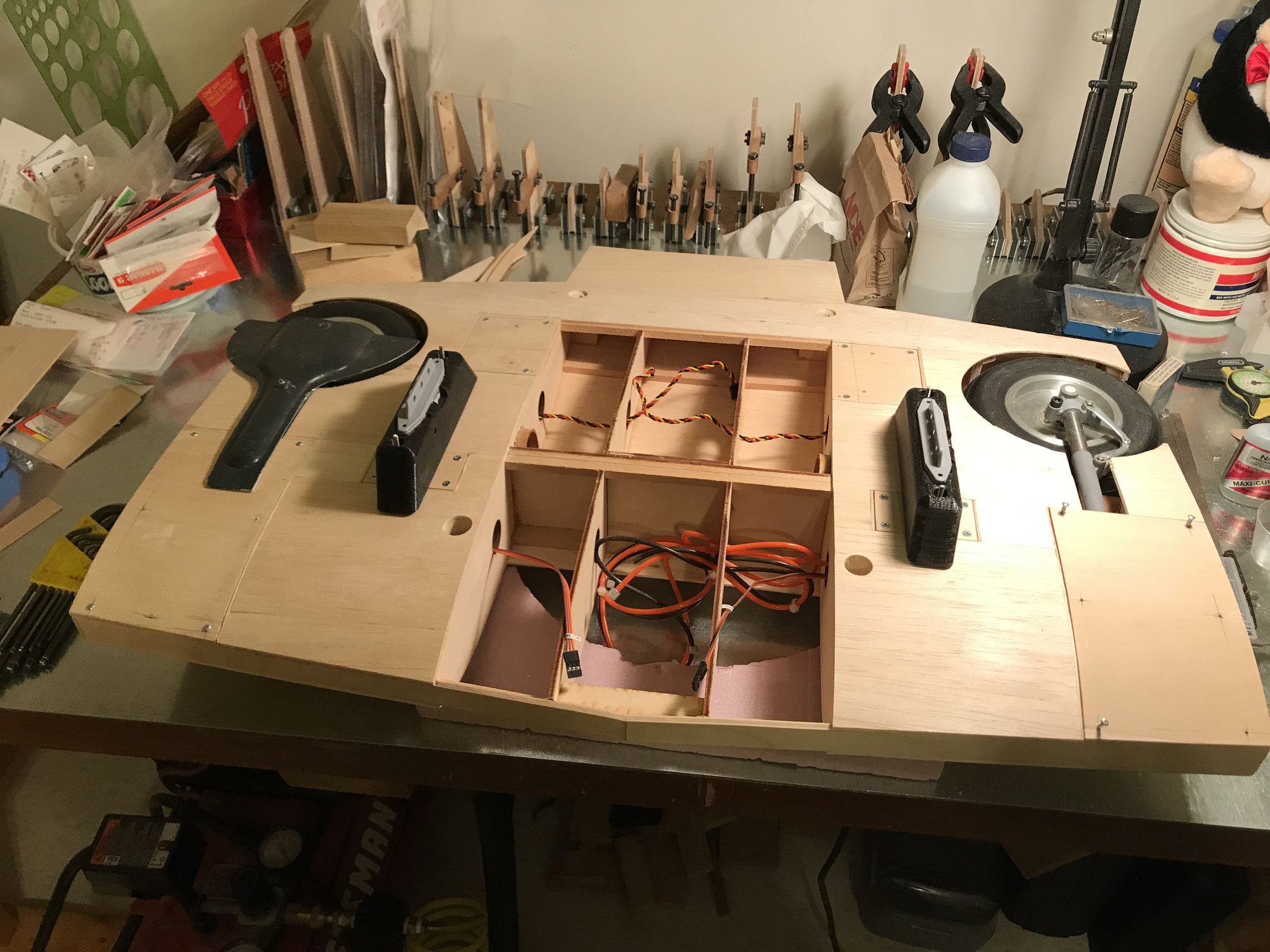
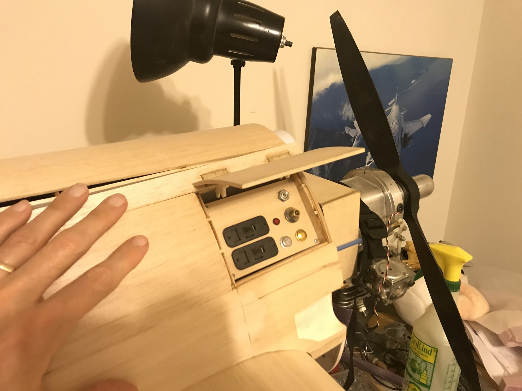
Fuel/Air/Electric Panel, ready for installation. 2 EDR-77N Balance charge switches with room for a third. Fuel extract and fill buttons at bottom right. LED from optical kill switch and air input valve, middle right and air pressure indicator at top right. Next, mount this in fuse behind firewall.
08-27-2018, 05:14 PM
#210
Thread Starter
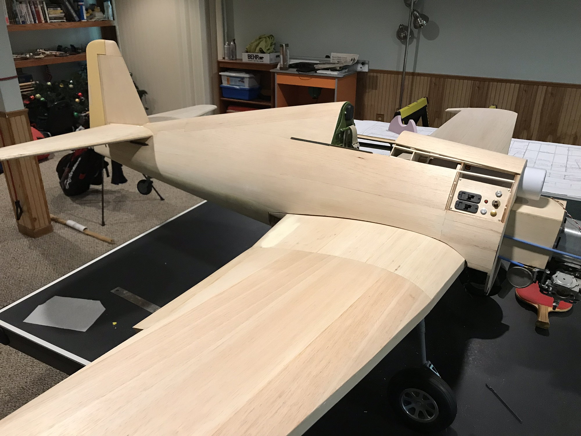
Switch/air/fuel panel installed and remaining stringers on right side of fuse. Stopped at LHS for some offset hatch hinges but no joy - will have to hunt online: Was in Iceland recently - didn't get to meet Sturla but did meet his best friend while watching the fire works in Rekyavik - we did make contact via email and will meet him on next trip.

09-03-2018, 12:05 PM
#211
Thread Starter
Sheeting the fuse - closing up! Left side stringers completed. Right side sheeted, except for access panel area - waiting on offset hinges to arrive. Will complete left side sheeting while waiting for them. using as few pieces as possible to complete the fuse sheeting - bit of a pain, but the end result is very good - I should have not filling required on the top-half of the fuse, unless I add some hangar rash.
Looking back through previous posts, see that I missed showing picture of completed throttle and choke setup - so, included picture, this time. With servo programmer hooked up, tested operation of each - they work just fine. Also decided on a new fuel tank - the old one will serve on my engine test stand.

Looking back through previous posts, see that I missed showing picture of completed throttle and choke setup - so, included picture, this time. With servo programmer hooked up, tested operation of each - they work just fine. Also decided on a new fuel tank - the old one will serve on my engine test stand.
09-29-2018, 08:44 AM
#212
Thread Starter
Still waiting on hatch hinges - going with another source - should be here next week.
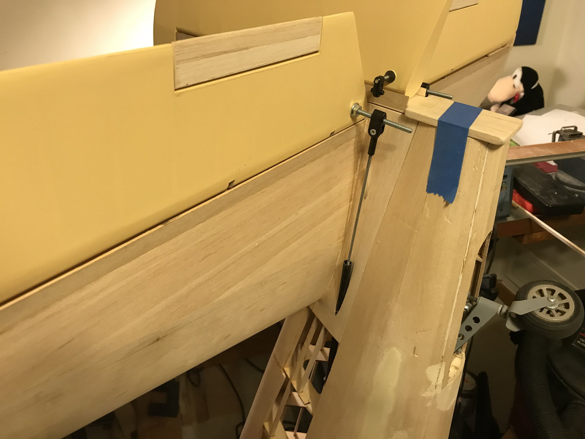
Working on filling in the space between the leading edge of the vertical fin and fuselage. Plans are a bit short, here, showing something that looks like a couple pieces of 1/8" sheet balsa cut to shape and glued in front of the fin:
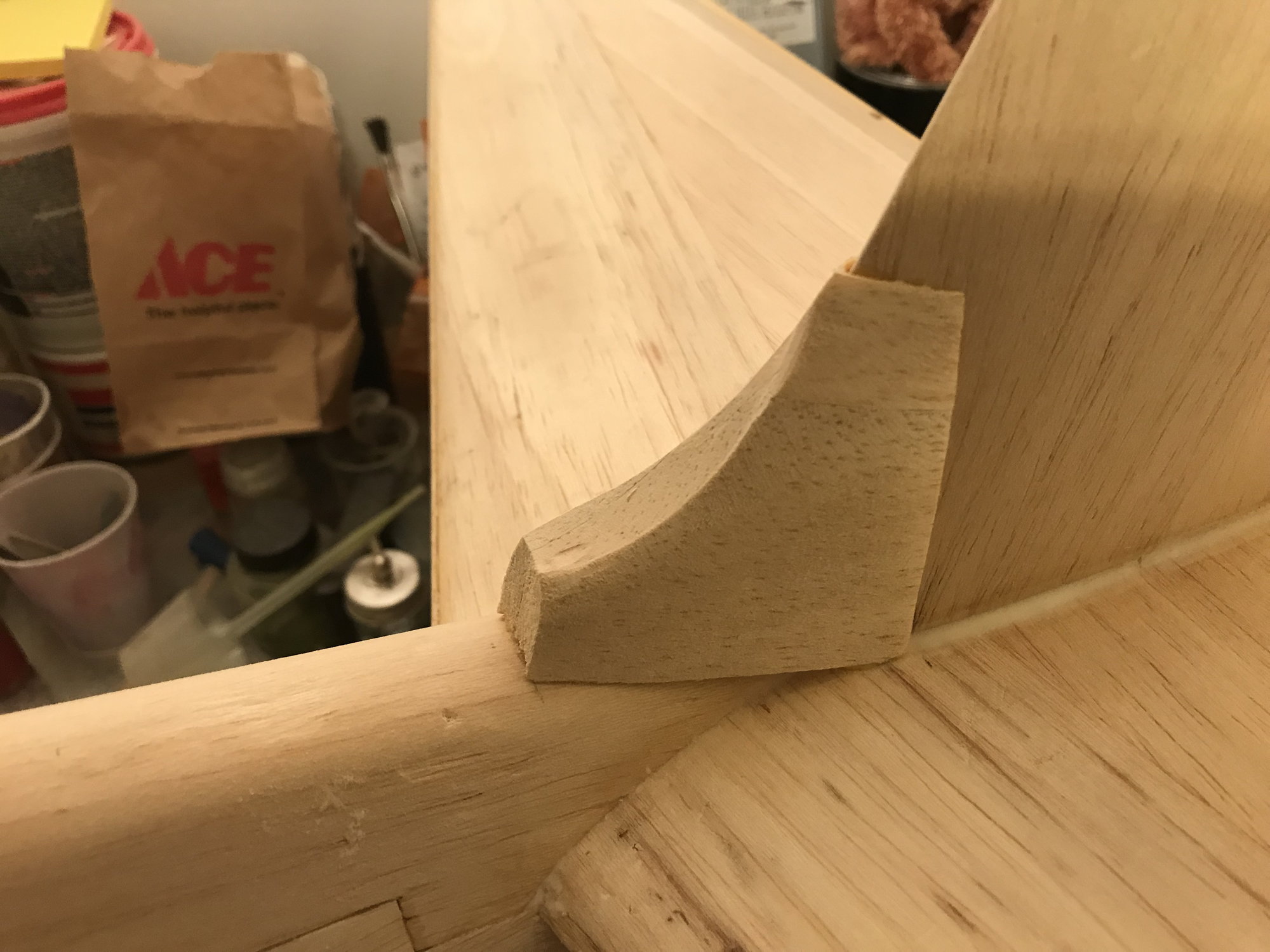
First block, hollowed (sanded) to fit fin.
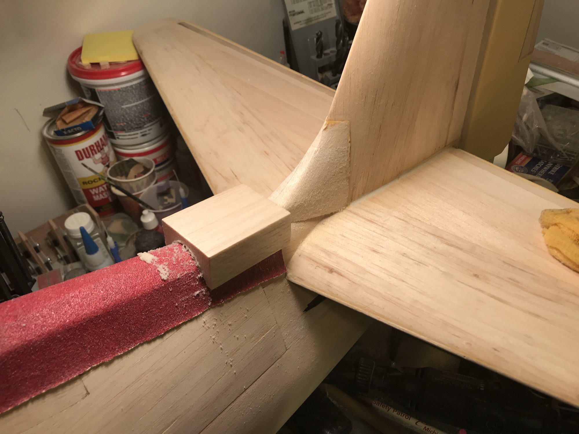
Sanding second block to fit fuse.
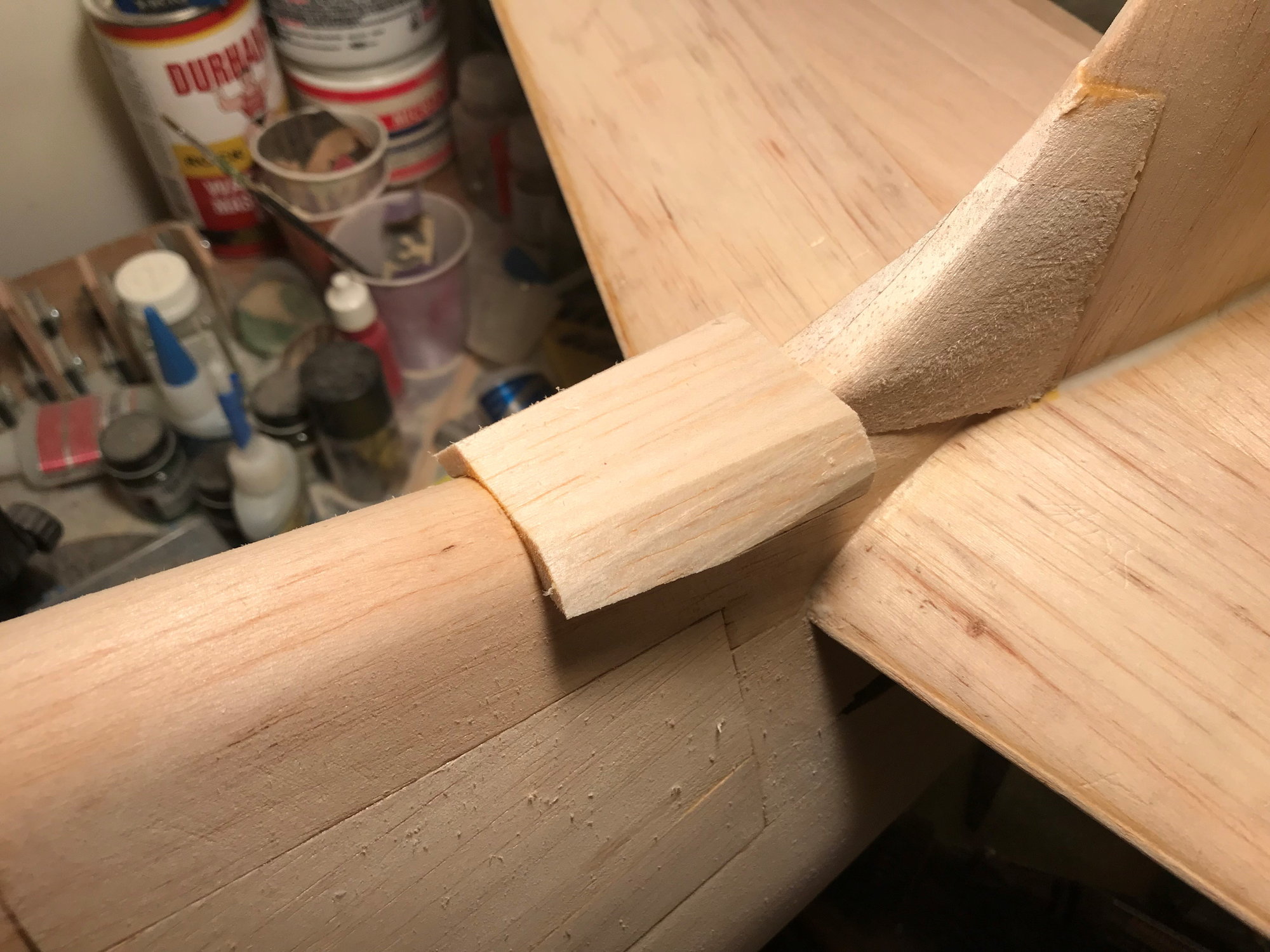
Used razor planer to remove most of the excess.
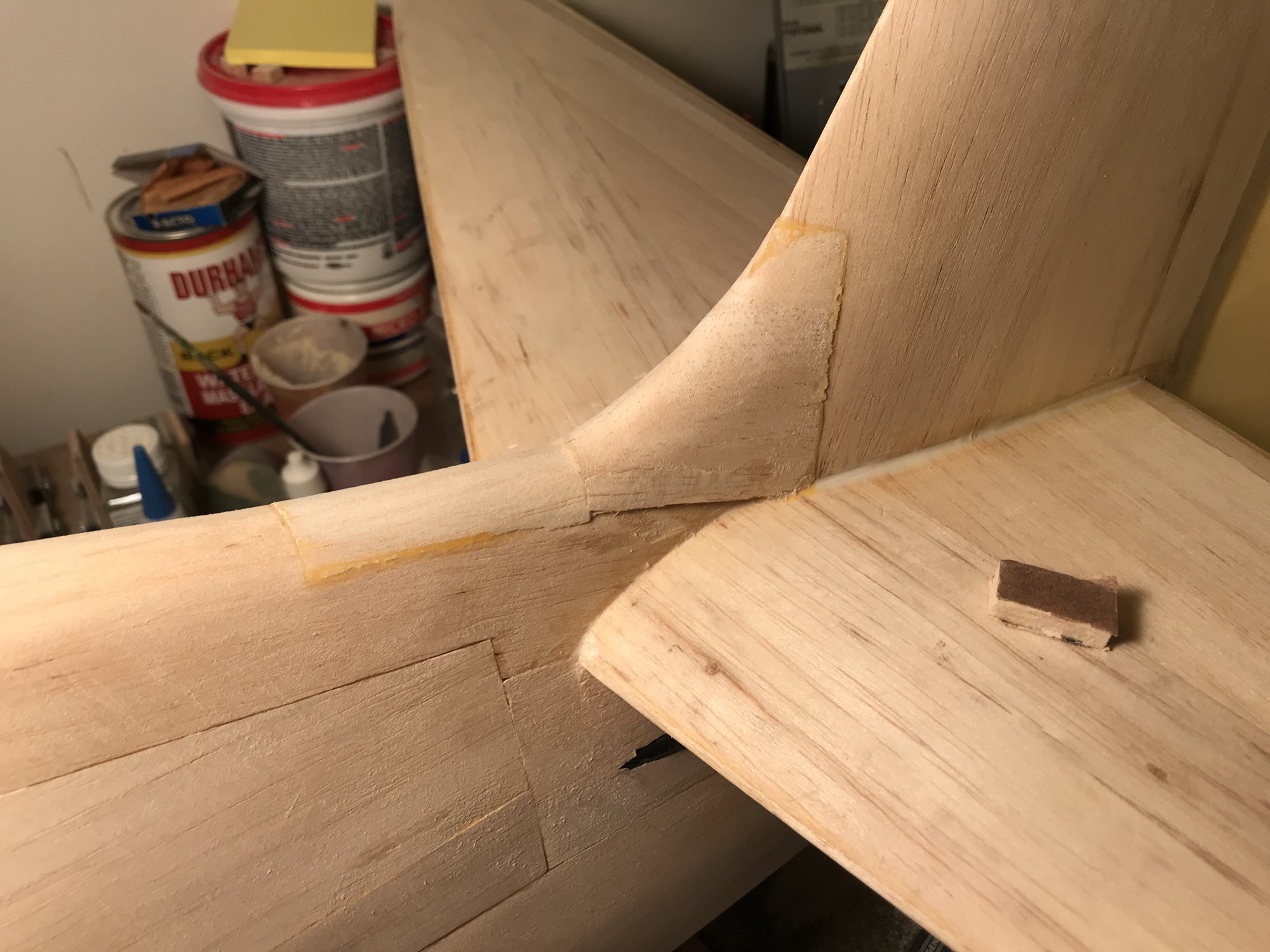
After lots of sanding, starting to shape up. Will fill with epoxy/microballoons to smooth out edges.
Working on filling in the space between the leading edge of the vertical fin and fuselage. Plans are a bit short, here, showing something that looks like a couple pieces of 1/8" sheet balsa cut to shape and glued in front of the fin:
First block, hollowed (sanded) to fit fin.
Sanding second block to fit fuse.
Used razor planer to remove most of the excess.
After lots of sanding, starting to shape up. Will fill with epoxy/microballoons to smooth out edges.
10-19-2018, 03:51 PM
#213
Thread Starter
Fin 'flair' done. Hatch hinges are still on backorder. Starting to carve/sand out the exhaust indents behind the cowling. Shaping still isn't a strong skill for me, so taking it slow, removing what doesn't look right. Want to get one done right and I should then have a method down and the next three will go faster.
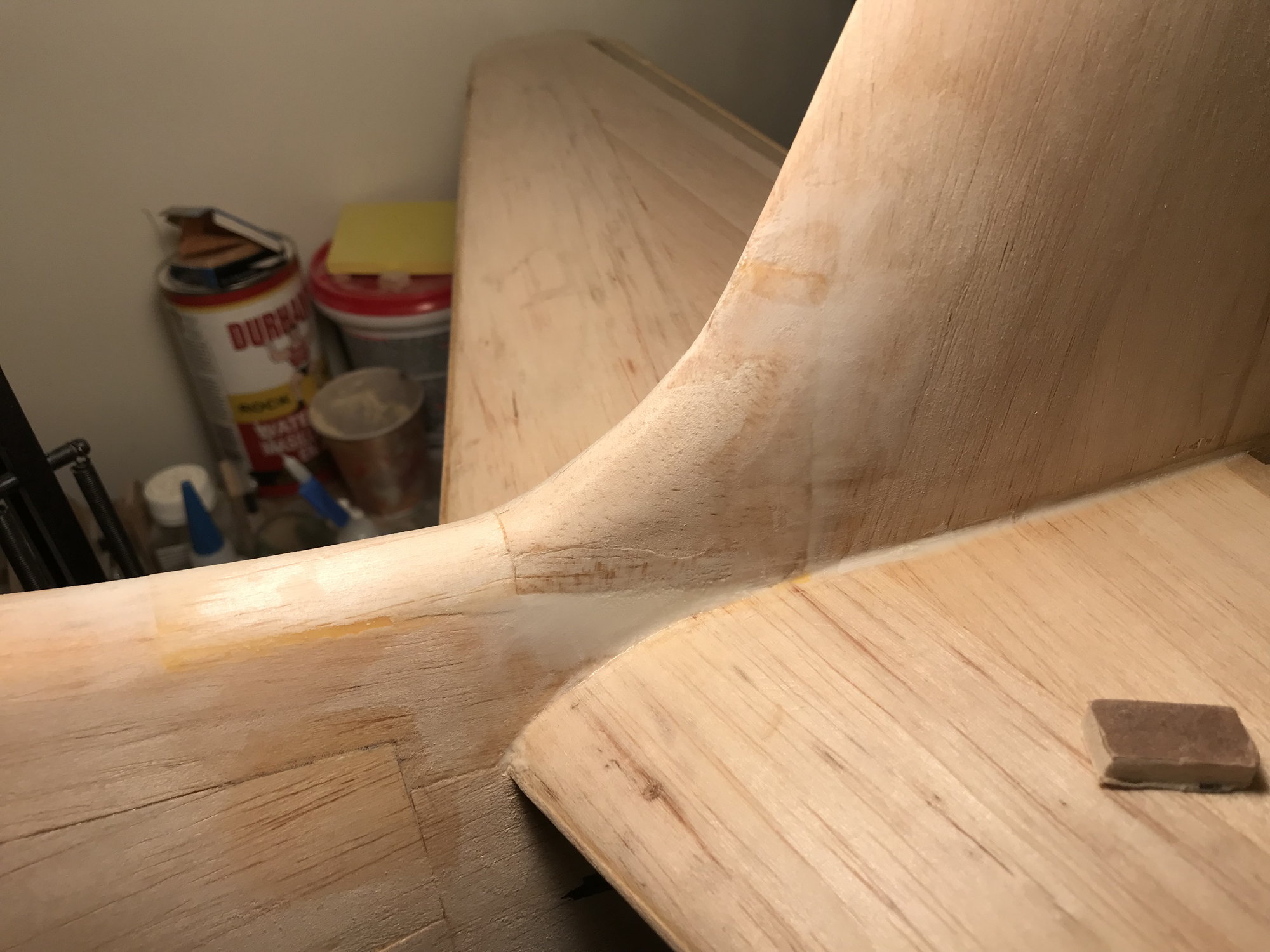
Fuse 'flair' into fin

Starting to carve/sand out exhaust detents
Fuse 'flair' into fin
Starting to carve/sand out exhaust detents
10-20-2018, 05:47 AM
#214

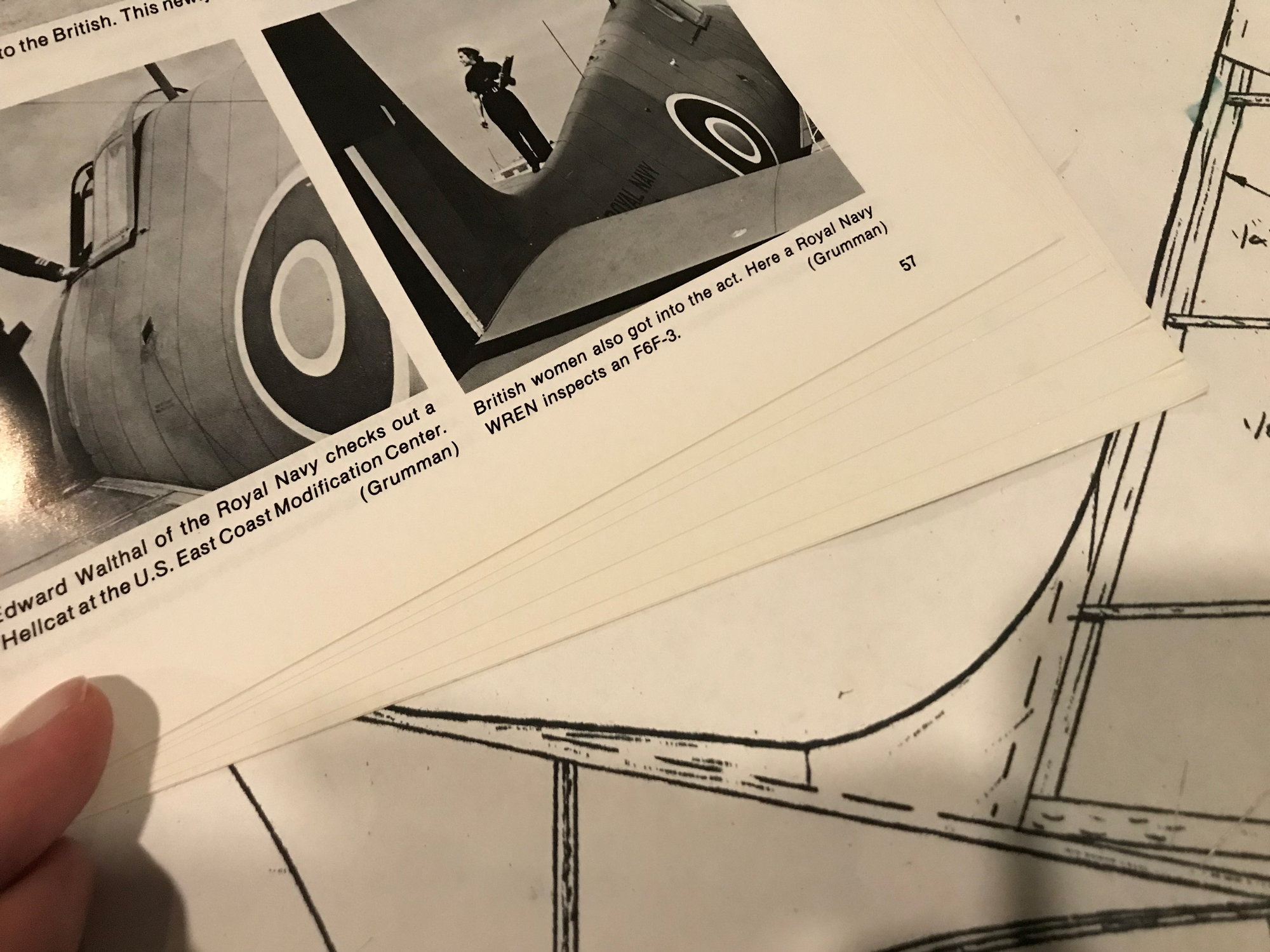
Truly enjoying your build. Looks like you are quickly moving along unlike me with my Charles Kellogg TBM Avenger here on RCU under Warbirds. I painted my Avenger in RAF Fleet Air Arm color scheme. I see the photos of the RAF Hellcat, is that the scheme you are going to use. Really appreciate Chad's wisdom, advice, and his products I also used in my build. Stay well and Stay safe everyone. Patiently observing your build. Chic
10-21-2018, 08:58 AM
#215
Thread Starter
Truly enjoying your build. Looks like you are quickly moving along unlike me with my Charles Kellogg TBM Avenger here on RCU under Warbirds. I painted my Avenger in RAF Fleet Air Arm color scheme. I see the photos of the RAF Hellcat, is that the scheme you are going to use. Really appreciate Chad's wisdom, advice, and his products I also used in my build. Stay well and Stay safe everyone. Patiently observing your build. Chic
At least that's the idea, and it seemed to generate interest from airshow guests when displaying my Byron.
I did see a "-5" in tri-color on the USS Yorktown (CV-10). Will have to think about which version of this pic I go with, this time - the white bottom would add some visual distinction up vs down.
Thanks again for your comments.
 10-21-2018, 09:39 AM
#217
Thread Starter
Exhaust cutouts are coming along, now that I have a technique that works for me. Left upper is done, with right upper about 50% completed. Both bottom cutouts are done, though I need to mount the belly pan to the fuse and finish matching the cutouts in the belly pan to those in the firewall. Should have done that back near the beginning of the project. Still not much of a carver, but "only remove what doesn't look right" is good advice.
There was quite a bit of end grain exposed in the upper cutouts, so I used the 'water putty and light spackle' mixture to smooth and seal. I could have kept sanding, but thought I had already taken out enough, didn't want to keep sanding and find out I had gone to far, making any filling/sanding job harder.


There was quite a bit of end grain exposed in the upper cutouts, so I used the 'water putty and light spackle' mixture to smooth and seal. I could have kept sanding, but thought I had already taken out enough, didn't want to keep sanding and find out I had gone to far, making any filling/sanding job harder.
Last edited by DaleCS; 10-21-2018 at 09:43 AM. Reason: Duplicate picture and forgot some text.
 12-02-2018, 03:39 PM
#220
Thread Starter
Have been working on fitting the belly pan to the rear, covered portion of the wing center section. Also, working on the front, underside of the wing center section. Once I have the front, center section underside coverer, will finish fitting the belly pan. Hinges for the switch/fuel/air access panel are still on backorder.
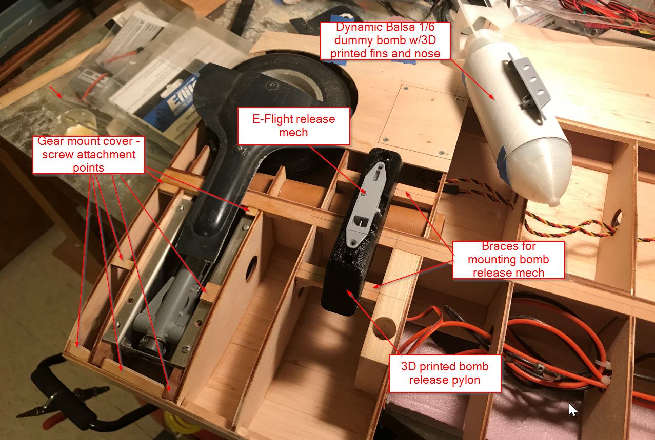
I'm going to create a removeable cover for the landing gear. If the gear is ever damaged or needs maintenance, I want easy access, without having to tear up the wing surface. Also, this will make threading the air lines for the gear and the servo wiring for the aileron and gun simulator LEDs much easier. Cover will be made of 3/32" thick basswood - more strength then balsa and will still curve nicely to the wing's underside shape.
For bomb pylon mounting, I'll use a blind nut under the mounting brace and solder a nut to some 4-40 threaded rod to make a 'hex bolt,' as I haven't found, yet, any 4-40 bolts/screws that are long enough for the job.
Was on the Dynamic Balsa website a couple weeks ago and did not see the 3D printed bomb pylons, there. If interested in buying a set, you may need to drop them an email.
12-16-2018, 11:45 AM
#221
Thread Starter
Left bottom center section almost done - just need to finish mounting of gear cover, complete the gear, wheel cutout and attach a bit of sheet balsa to the back half of the bomb release pylon and sand to shape of wing underside. Then, complete right side. Also, I'm going to solder a nut to the top of each 4-40 rod and then cut a slot across the top using a cut-off wheel - basically, creating a 2-1/4" 4-40 bolt.

12-18-2018, 06:08 PM
#222
Thread Starter
Right underside of wing center section all but done. Need to finish cutouts for both gear and wheels, and sand filler balsa piece on bomb release pylons to fit wing curvature. Then, will need to learn how to make my own gear door covers as the Byron covers don't have a deep enough 'well' - the Byron wing thickness must have been a bit thicker, as there is about an 1/8" gap between the gear door and the bottom of the wing - and there's no space to retract the gear deeper into the well.
Leaving center section open for now - may use space for receiver, batteries, smoke pump...

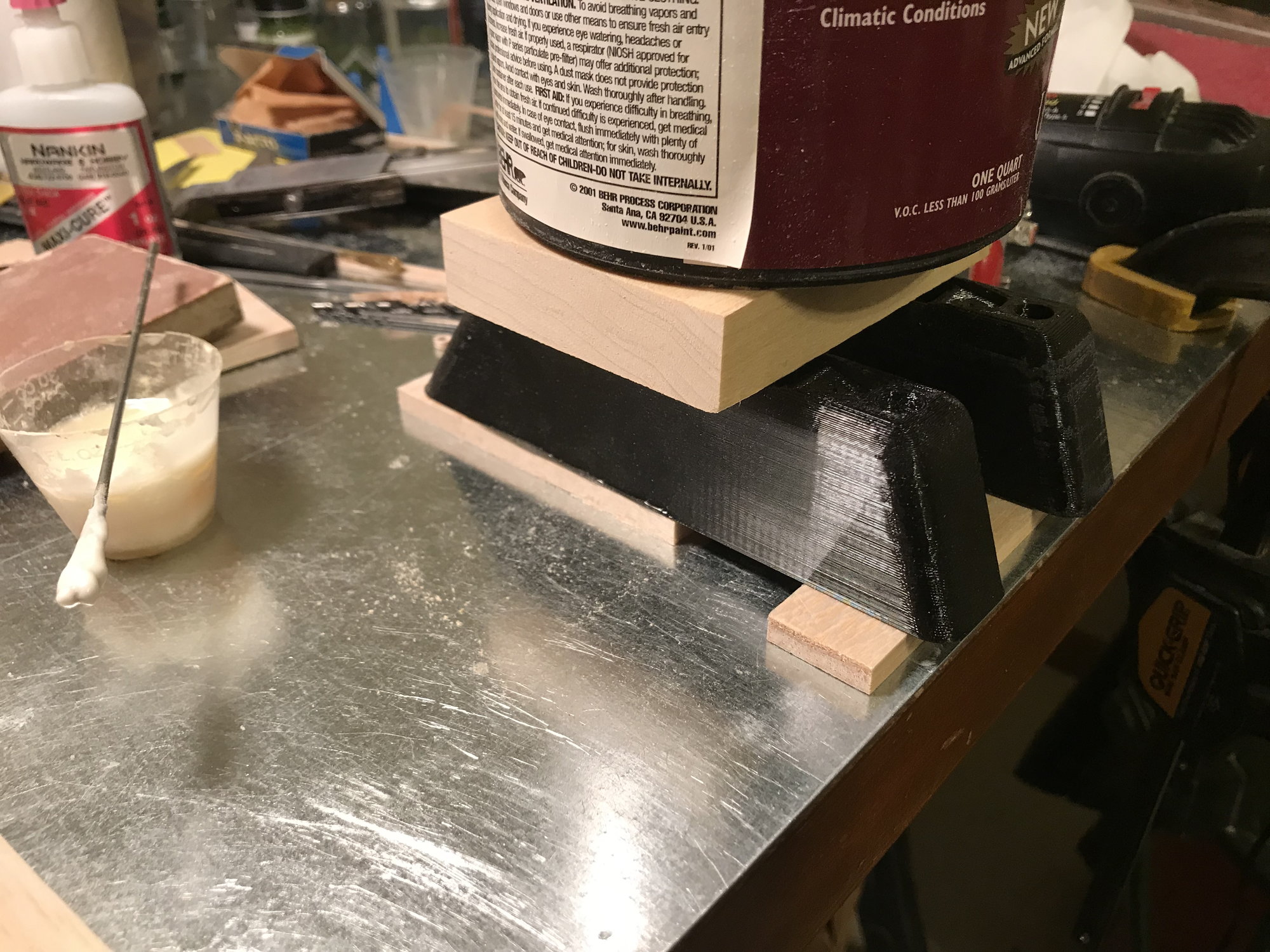
Attaching balsa filler blocks to the back 2/3's of the bomb release pylons. The pylons were 3D printed, from Dynamic Balsa. Will lay some sandpaper on the wing and sand the filler to the shape of the wing.
Leaving center section open for now - may use space for receiver, batteries, smoke pump...
Attaching balsa filler blocks to the back 2/3's of the bomb release pylons. The pylons were 3D printed, from Dynamic Balsa. Will lay some sandpaper on the wing and sand the filler to the shape of the wing.
02-01-2019, 06:57 PM
#223
Thread Starter
Wing center section - bottom sheeted, bomb pylons fitted and removeable gear bay covers fitted. Haven't posted anything, lately, due to some home repair projects and winter illnesses.
Struggling a bit with ideas for mounting the belly pan. Have been sanding edges to fit curvature of wing center section underside - getting close to having this done. Wanted a 'blind' mount where screws/bolts wouldn't be visible. Nylon bolts, or even steel (for balance purposes) through the firewall at the front are an obvious choice. But holding up the rear portion of the pan, I'm a bit stuck. Had though of dowel pins, through the rear pan former into the mating fuse former, but not seeing how this is going to work, not that I'm fitting, moving parts around. Maybe if the were spring loaded pins....but how to retract them when I need to remove the pan?
Have seen where some have glued the pan to the wing center section, then have holes cut for accessing the 4 wing mounting bolts. Would like to avoid these holes.
Ideas? If you have examples, please attach a link in your comments.
BTW: Looks like my wheel covers leftover from my Byron won't work - the 'pocket' isn't deep enough, so the covers aren't flush with the wing bottom.
Thanks!
06-29-2019, 10:31 AM
#224
Thread Starter
A bit more done, after a significant piece of time. RC has been dropping in priority over the last few years, due to a number of reasons, as anyone still following this thread can see. But, I am still interested. I do want to finish what I started. I did get some time, recently, to make some progress.
- Belly pan rough fit to fuse/wing center section completed. I've settled on means to mount this, using a couple screws at either end - two at angles through blocks in the belly pan, into the backside of the firewall, and another two in same manner at the rear of the pan. Not the 'blind mount' that I'd like, but need to keep moving, this will be 'good enough' and will still allow quick access to the wing mounting bolts without too much trouble. If anyone has a better idea, let me know.
- Fuel, air, electrical access panel - well underway. Just need to mount to fuse and complete fit/finish. Wanted offset hinges for a blind hinge mount, and these work great when the materials one is working with are thin, like a sheet of plastic or fiberglass. On 1/8" sheet, not so easy. In order to get a small hinge gap, I recessed some 1/32" ply pieces in the balsa exterior surface, then hollowed out the back side of the sheet to recess the hinges, trying to get them as close to the sheet's exterior surface as possible. In addition, I'll have to due some edge work, creating a concave surface on the hatch edge, and a matching convex edge on the fixed edge. Not the simplest design, but I'm well into it. IFF (IF and only iF) this doesn't work satisfactorily, I will at least have some nice surfaces made up that I can use for laying up some fiberglass for a thin hatch cover.
I want to complete the hatch assembly and then one last fitment of balsa sheet will have the fuse closed up. Then, I need to fit the cowling. I have a Don Smith cowling - the profile at its back doesn't fit the the shape of the Ziroli (reduce to 1/6) firewall, as I've mentioned before. Also, the Top Flight 1/6 Hellcat cowling, from pictures, appears to have the same profile as the Don Smith cowling. I don't have an cross-section view from an actual Hellcat, but from the drawings and pics that I do have, I'm starting to believe that maybe the firewall on my 1/6 Ziroli is wrong, that its "tending toward tear drop shape" is wrong and that it should be more like the Don Smith/Top Flight designs (and what I remember from the Byron).
Rather than cutup a purchased cowling, I'm probably better off adding some edge work to the firewall to have it match the off the shelf cowlings. Cowlings get damaged - if I need to replace one, I'd like to paint it and throw it on, and not have to cut it, reshape, ......
Before finishing my access hatch, by writing this post, I think I just changed my plans..... I need to get the firewall and cowling fit first as this will alter the shape of my access hatch. Thankfully, it's balsa and can be reformed - can use what I've got, no need to start over.
View of hatch assembly's interior side:

Holding hatch assembly into place by hand:
- Belly pan rough fit to fuse/wing center section completed. I've settled on means to mount this, using a couple screws at either end - two at angles through blocks in the belly pan, into the backside of the firewall, and another two in same manner at the rear of the pan. Not the 'blind mount' that I'd like, but need to keep moving, this will be 'good enough' and will still allow quick access to the wing mounting bolts without too much trouble. If anyone has a better idea, let me know.
- Fuel, air, electrical access panel - well underway. Just need to mount to fuse and complete fit/finish. Wanted offset hinges for a blind hinge mount, and these work great when the materials one is working with are thin, like a sheet of plastic or fiberglass. On 1/8" sheet, not so easy. In order to get a small hinge gap, I recessed some 1/32" ply pieces in the balsa exterior surface, then hollowed out the back side of the sheet to recess the hinges, trying to get them as close to the sheet's exterior surface as possible. In addition, I'll have to due some edge work, creating a concave surface on the hatch edge, and a matching convex edge on the fixed edge. Not the simplest design, but I'm well into it. IFF (IF and only iF) this doesn't work satisfactorily, I will at least have some nice surfaces made up that I can use for laying up some fiberglass for a thin hatch cover.
I want to complete the hatch assembly and then one last fitment of balsa sheet will have the fuse closed up. Then, I need to fit the cowling. I have a Don Smith cowling - the profile at its back doesn't fit the the shape of the Ziroli (reduce to 1/6) firewall, as I've mentioned before. Also, the Top Flight 1/6 Hellcat cowling, from pictures, appears to have the same profile as the Don Smith cowling. I don't have an cross-section view from an actual Hellcat, but from the drawings and pics that I do have, I'm starting to believe that maybe the firewall on my 1/6 Ziroli is wrong, that its "tending toward tear drop shape" is wrong and that it should be more like the Don Smith/Top Flight designs (and what I remember from the Byron).
Rather than cutup a purchased cowling, I'm probably better off adding some edge work to the firewall to have it match the off the shelf cowlings. Cowlings get damaged - if I need to replace one, I'd like to paint it and throw it on, and not have to cut it, reshape, ......
Before finishing my access hatch, by writing this post, I think I just changed my plans..... I need to get the firewall and cowling fit first as this will alter the shape of my access hatch. Thankfully, it's balsa and can be reformed - can use what I've got, no need to start over.
View of hatch assembly's interior side:
Holding hatch assembly into place by hand:
07-07-2019, 02:43 PM
#225
Thread Starter
Did it - got the TF 1/6 Hellcat Cowl and drop tank. Figured I'd go with a company that has a higher likelihood of being around, longer and easy to deal with. Glad I did. Cowling is very well shaped, all the trim work is done and it came with a interior former that is helping me figure out how to mount and reshape the front end to fit it.
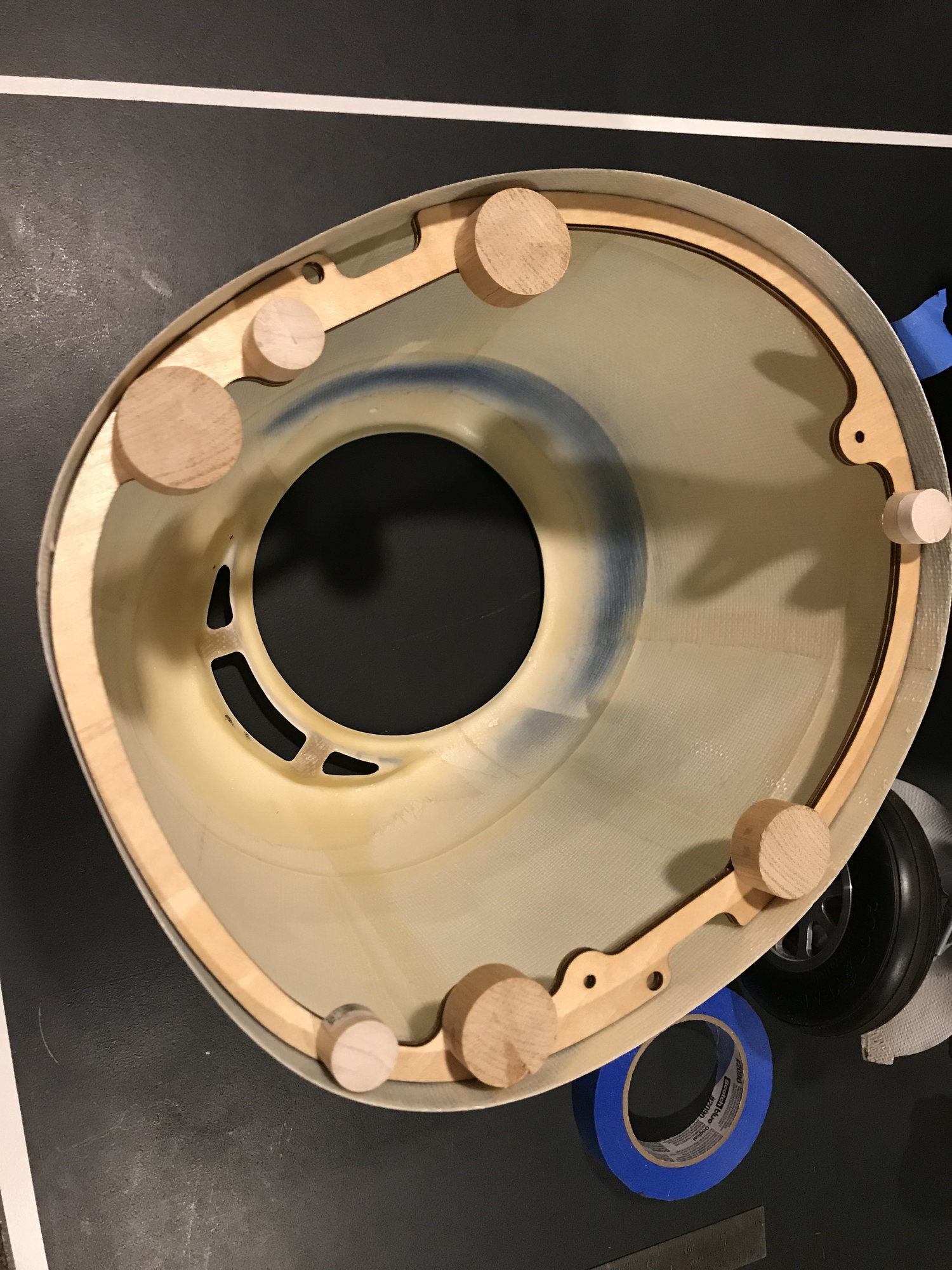
Interior former pressed in place, with some stand-offs that I made, to be drill out.
Interior former taped to firewall, highlighting shape differences. Wished I had been able to get this cowling at the start of the project, but TF 1/6 Hellcat wasn't available then. Had it been, I probably would have gotten it and put my own paint scheme to it.
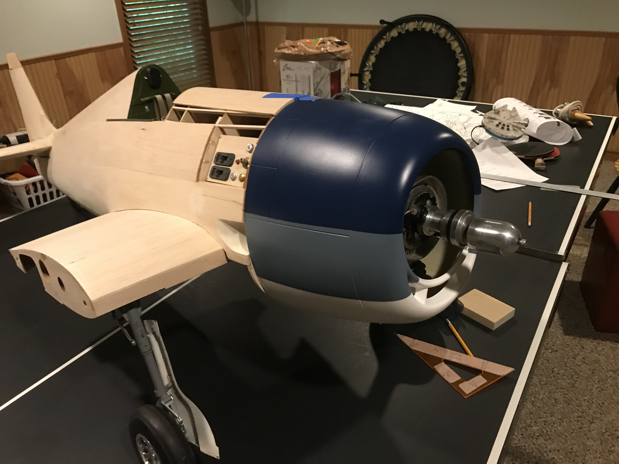
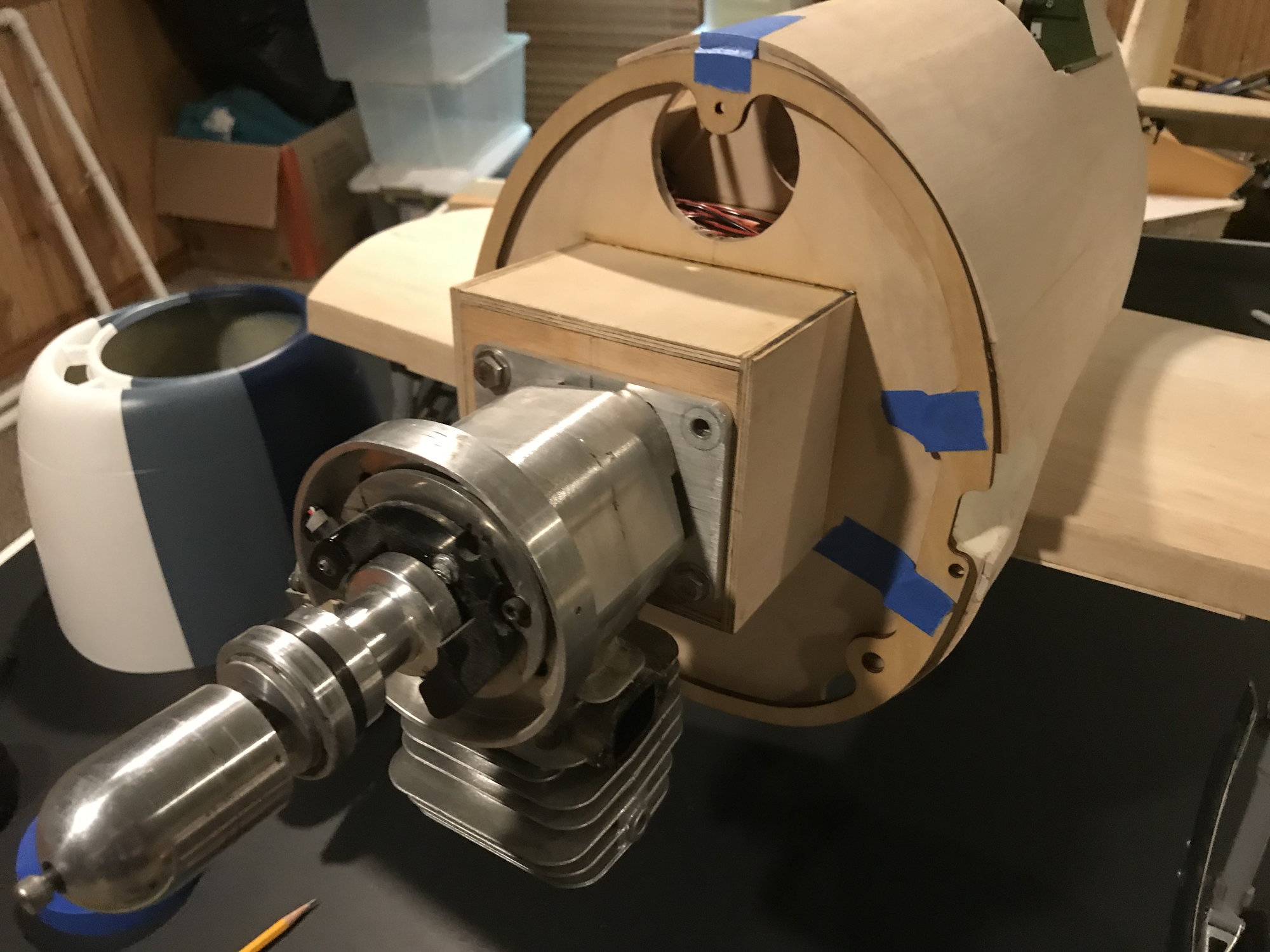
Taped in place. Unfortunately, this identified more work for me, as the center engine open for this cowling is a bit higher than the one I used for mounting the engine. The engine will need to move up a bit. Well, I'll at least get more ground clearance for the prop!

Stand-offs drilled, dowel plugs fitted end epoxied to the former. Next step, epoxy the former into the cowling
Interior former pressed in place, with some stand-offs that I made, to be drill out.
Interior former taped to firewall, highlighting shape differences. Wished I had been able to get this cowling at the start of the project, but TF 1/6 Hellcat wasn't available then. Had it been, I probably would have gotten it and put my own paint scheme to it.
Taped in place. Unfortunately, this identified more work for me, as the center engine open for this cowling is a bit higher than the one I used for mounting the engine. The engine will need to move up a bit. Well, I'll at least get more ground clearance for the prop!
Stand-offs drilled, dowel plugs fitted end epoxied to the former. Next step, epoxy the former into the cowling